3
Copyright © 2020 Quality Machine Tools, LLCPM-1440GT v9 2020-10
Section 1 INSTALLATION
THESE ARE THE MAIN POINTS TO WATCH OUT FOR!
But read the following pages for more information
• Handling the lathe is at least a two-person job.
• Lifting gear – sling, hoist or forklift – must be rated for at least 1-1/2 tons.
• Working location of the lathe must allow space for removal of the belt cover at left; also,
access to the coolant system (back of right hand cabinet) and the electrical box at the
back of the headstock.
• Power requirement is 220V, 60Hz, 1φ (3φ optional).
• Extension cords are not to be used.
• Before connecting power, be sure that:
1. The machine is on a rm footing.
2. Chuck camlocks tight, no wrench left in chuck.
3. Saddle and cross-slide approx. mid-travel, power feeds are disengaged (Figure 1-8).
4. The headstock gear selectors are set for the lowest spindle speed.
SETTING UP THE LATHE
The PM-1440GT is shipped fully assembled in a single pack-
ing case. The machine can be lifted in one piece by an over-
head hoist or forklift with slings and/or chains, all items rated
for a total weight of at least 1-1/2 tons. A suggested setup for
lifting is shown in Figure 1-1.
When selecting a location for the lathe, allow sucient room at
the right to allow removal/servicing of the leadscrew, feed shaft
and motor control shaft.
Be sure to keep all lifting gear clear of any part of the
lathe, especially the 3 shafts at the front. Use at least 2-by
spreaders.
Figure 1-3 Coolant tank
Figure 1-1 Lifting with slings
Spreader under the bed
keeps slings/chains clear
of feed shafts, etc.
Before lifting, remove the chuck, if installed, then move the
tailstock and saddle as far to the right as possible to balance
the machine at the point(s) of suspension.
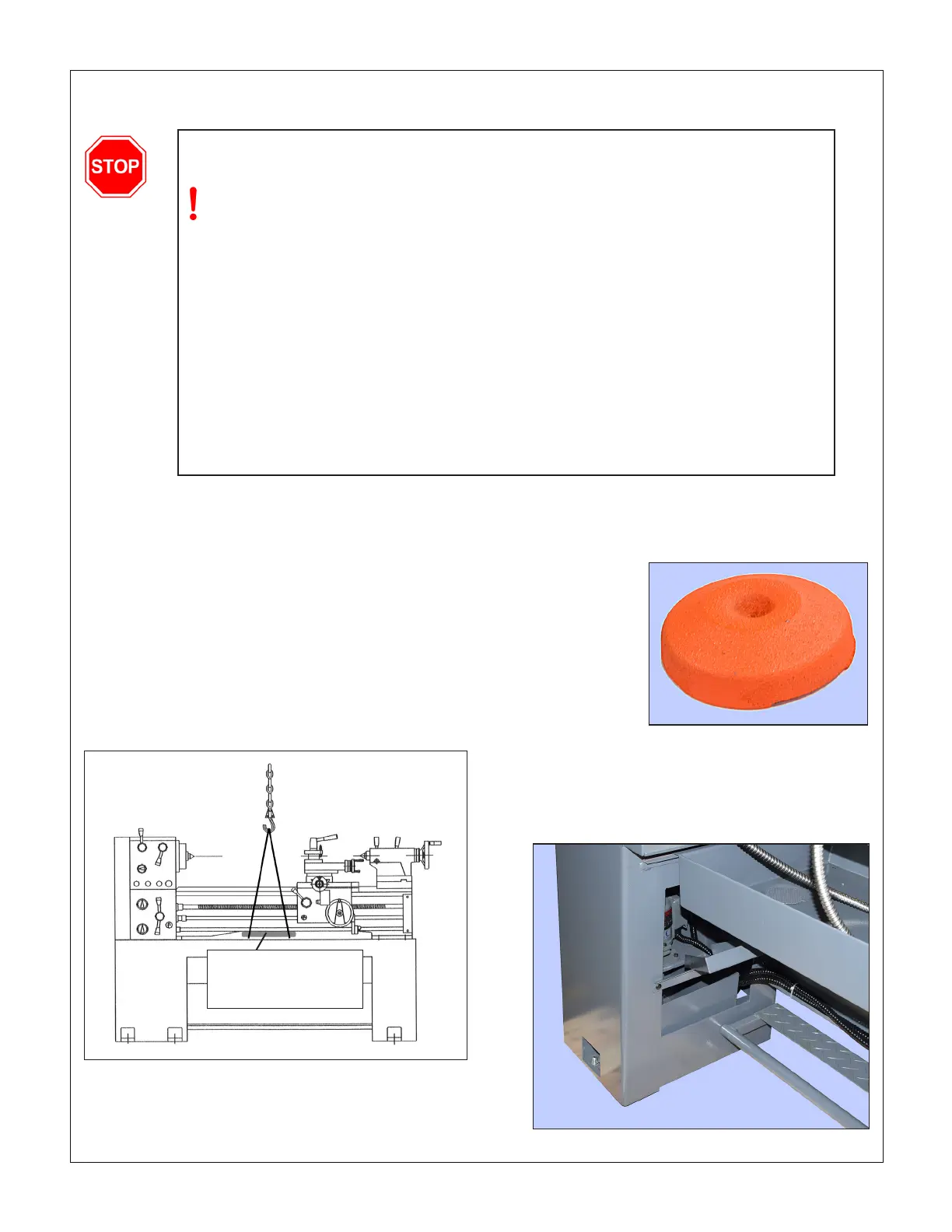
With the machine in its permanent location, lower it so that its
height adjustment bolts rest on the six supplied cast iron level-
ing mounts, Figure 2.
Inspect the coolant tank and pump assembly in the RH cabi-
net, Figure 1-3. The tank may have become dislodged in ship-
ment. Level it if necessary.
Figure 1-2 Leveling mount
Check oil levels in all gearboxes before use

 Loading...

