31
Copyright © 2020 Quality Machine Tools, LLCPM-1440GT v9 2020-10
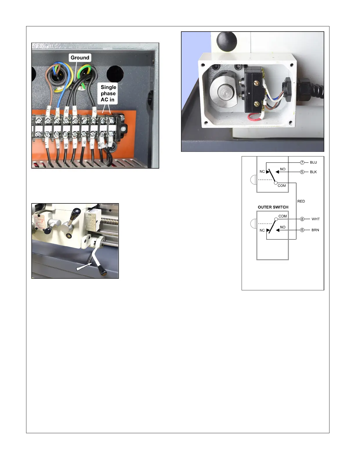
ELECTRICAL CONNECTIONS
Motor control lever
Mid-travel OFF, Down FORWARD, Up REVERSE
To change direction ...
See the previous page photos (wire colors vary). Do not disturb
the lower row of terminals (mostly red wires). For REVERSE
rotation when the motor control lever is moved down, discon-
nect ac power, then remove the cover from the motor control
switch box at the tailstock end. Note the colors of wires #5 and
#6. Conrm that these are same wires #5 and #6 on the termi-
nal block shown on the previous page. If so, swap only those
two wires on the terminal block, leaving the other #5 wire in
place for forward jog. For reverse jog, move the other #5 wire
to the #6 terminal.
DRO power
Low-wattage 110Vac power is available at R1, S1 on the upper
terminal strip, preceding page.
As shipped, the motor control switch is wired to select FOR-
WARD spindle rotation when the lever is DOWN. The JOG
push-button is also wired for forward rotation.
Single phase 220Vac connections
For three-phase AC, a third wire (T) is connected to the left of R, S.
MOTOR CONTROL WIRING
Motor control switches
Wire colors may
not be as shown
 Loading...


