25
Copyright © 2020 Quality Machine Tools, LLCPM-1440GT v9 2020-10
BRAKE ASSEMBLY
The treadle-operated brake does two things: 1. It disconnects
power from the motor, and; 2. It expands brake shoes against
the hollowed-out inboard face of the driven pulley.
Inspection of the brake assembly, Figure 4-16, calls for person
A to lock the driven pulley while person B removes the hex nut
securing the driven pulley.
The inboard face of the driven pulley (the brake drum) should
show no gouging or irregularities. Minor damage may be cor-
rectable by skimming; otherwise consider replacing the item.
The brake pads should be clean, evenly worn, showing no sign
of oil. Minimum pad thickness is 4.5 mm, about 0.18". If nec-
essary replace the pads by separating them — extending the
springs — then lifting them clear of the retaining studs.
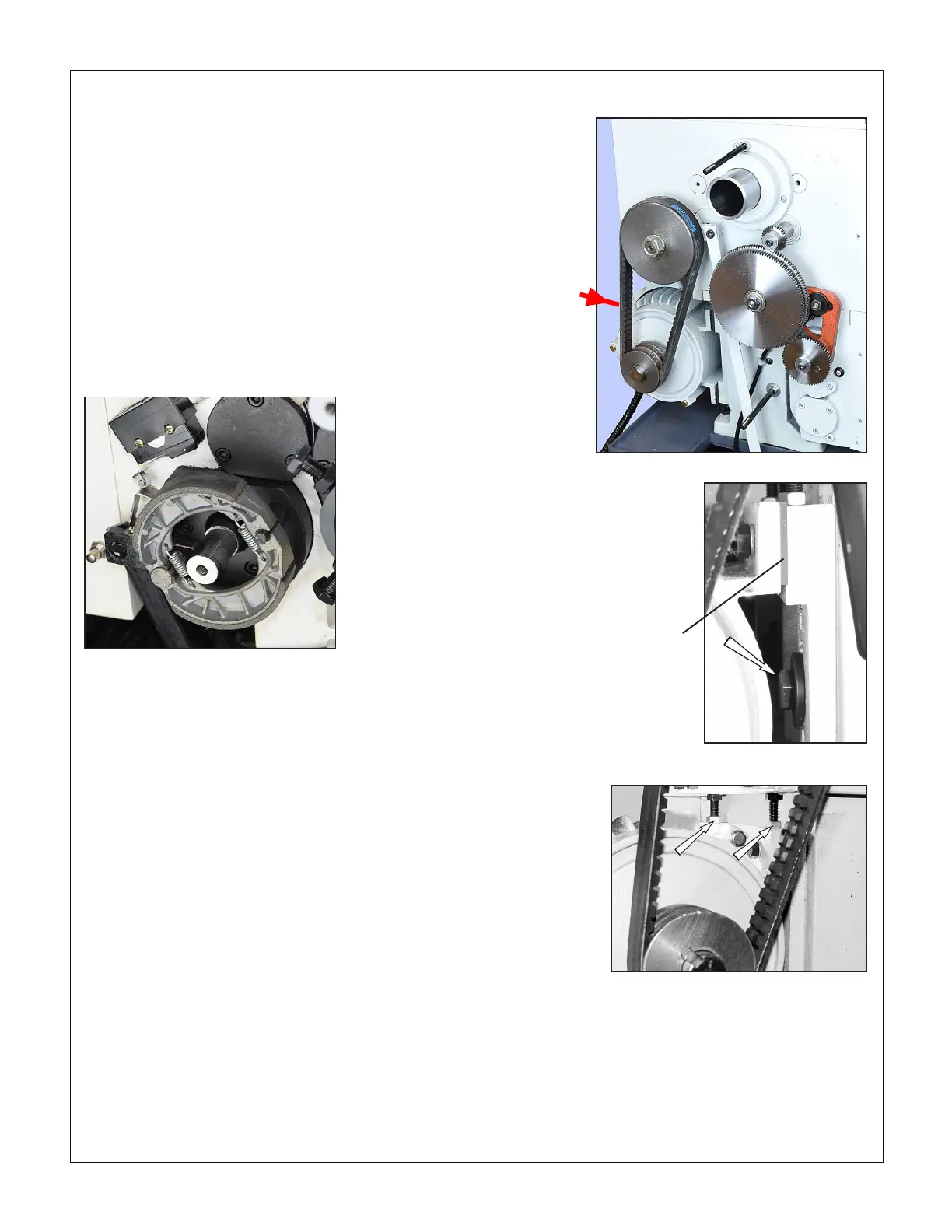
Figure 4-16 Brake assembly (representative)
Firm nger
pressure here
should deect
the Vee belt
about 1/4"
DRIVE BELT ADJUSTMENT
Figure 4-17 Test for belt tension
Figure 4-18 Motor frame bolts
Figure 4-19 Motor frame pusher screws
Vibration
damper
Loosen the two hex-head bolts securing the motor frame to the
headstock, Figure 4-18. Loosen the lock nuts on the pusher
screws, Figure 4-19, then adjust the screws to achieve the de-
sired belt tension. Re-tighten the lock nuts.

 Loading...

