9
Copyright © 2020 Quality Machine Tools, LLCPM-1440GT v9 2020-10
Section 3 USING THE LATHE
DRIVE TRAIN
Double-groove pulleys connect the motor to the gearbox, Fig-
ure 3-3. Belt tension will not usually require attention. If adjust-
ment is necessary, see Section 4.
What is not in this section ...
The PM-1440GT is a conventional engine lathe that requires
little explanation except for details specic to this particular
model — speed selection, thread cutting, and the saddle/
cross-slide power feed system. Because the user is assumed
to be familiar with general purpose metal lathes, this section
contains very little tutorial.
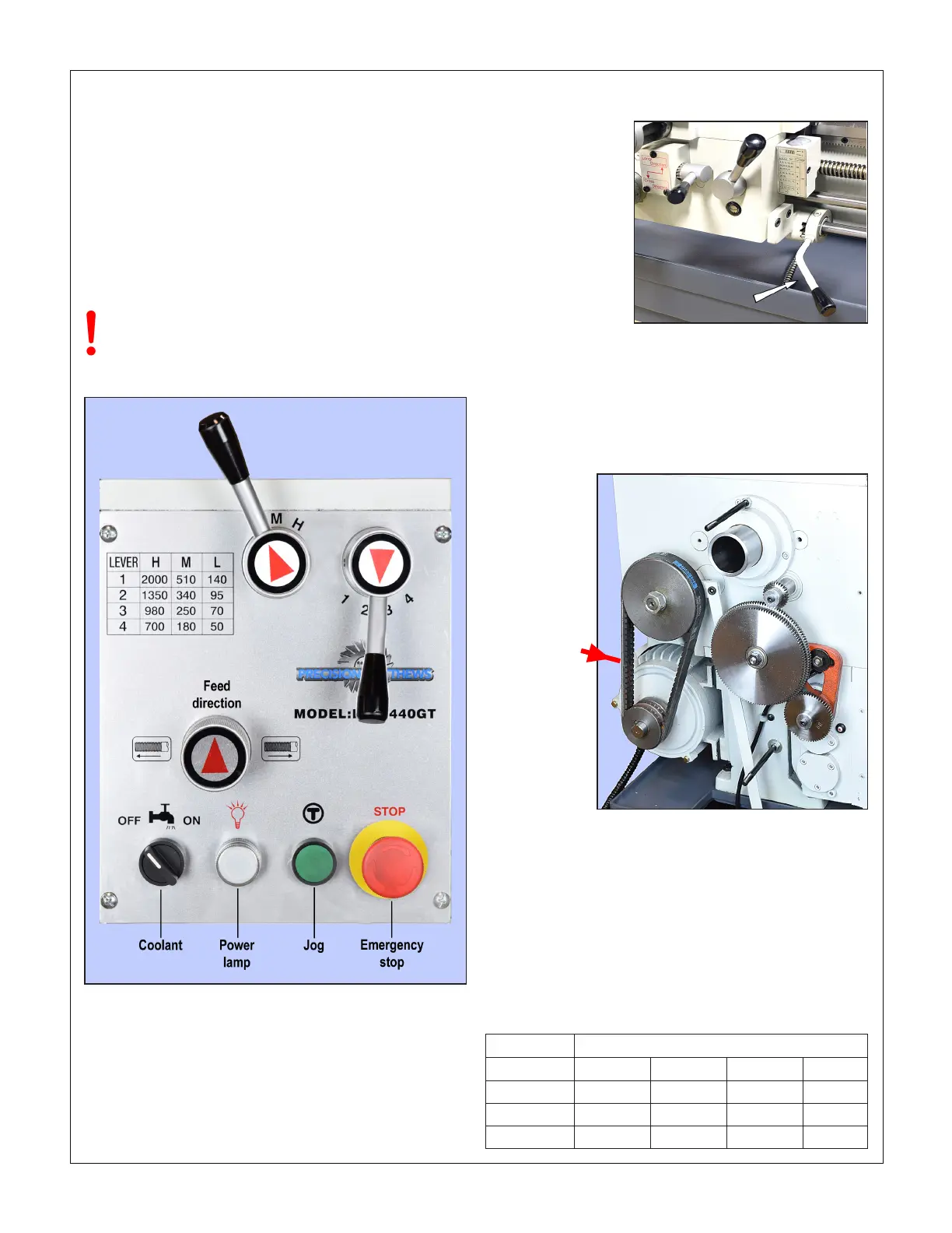
MOTOR CONTROLS Figure 3-1
Figure 3-1 Main control panel
Before doing ANYTHING, check the installation
instructions and power-up procedure in Section 1
STOP the motor before changing speed
Don't use JOG unless the gears are fully meshed
Figure 3-3 Vee belts & external change gears
Figure 3-2 Motor control lever
Mid-travel OFF, Down FORWARD, Up REVERSE
Before connecting power to the lathe, be sure the Motor Con-
trol Lever on the apron is set to OFF, Figure 3-2. Connect the
lathe to a 220 Vac outlet — the POWER lamp should light —
then operate the Motor Control Lever to run the spindle in the
desired direction.
Check that the E-Stop button and Footbrake interlocks func-
tion correctly.
Firm nger
pressure here
should deect
the Vee belt
about 1/4"
SPINDLE SPEEDS
The PM-1440GT has a twelve-speed headstock gearbox with
two shift levers, L-M-H & 1-2-3-4 (Speed Selection), Figure
3-1. Before changing speed, use the Motor Control, Figure
3-2, to STOP THE MOTOR, then move the shift levers to the
desired setting. This may need a little patience because it is
not always possible to go directly from one mesh to another.
Move the spindle back and forth by hand while trying to ease
the lever into its detent (meshed) position. Don’t use the JOG
button in this process — this may cause gear damage.
SPINDLE SPEED (RPM)
1 2 3 4
H RANGE 2000 1350 980 700
M RANGE 510 340 250 180
L RANGE 140 95 70 50

 Loading...

