4
Copyright © 2020 Quality Machine Tools, LLCPM-1440GT v9 2020-10
POWER CONNECTION
As shipped. the PM-1440GT is set for 220 V single or three-
phase.
Read Initial Checks, below, before connecting power
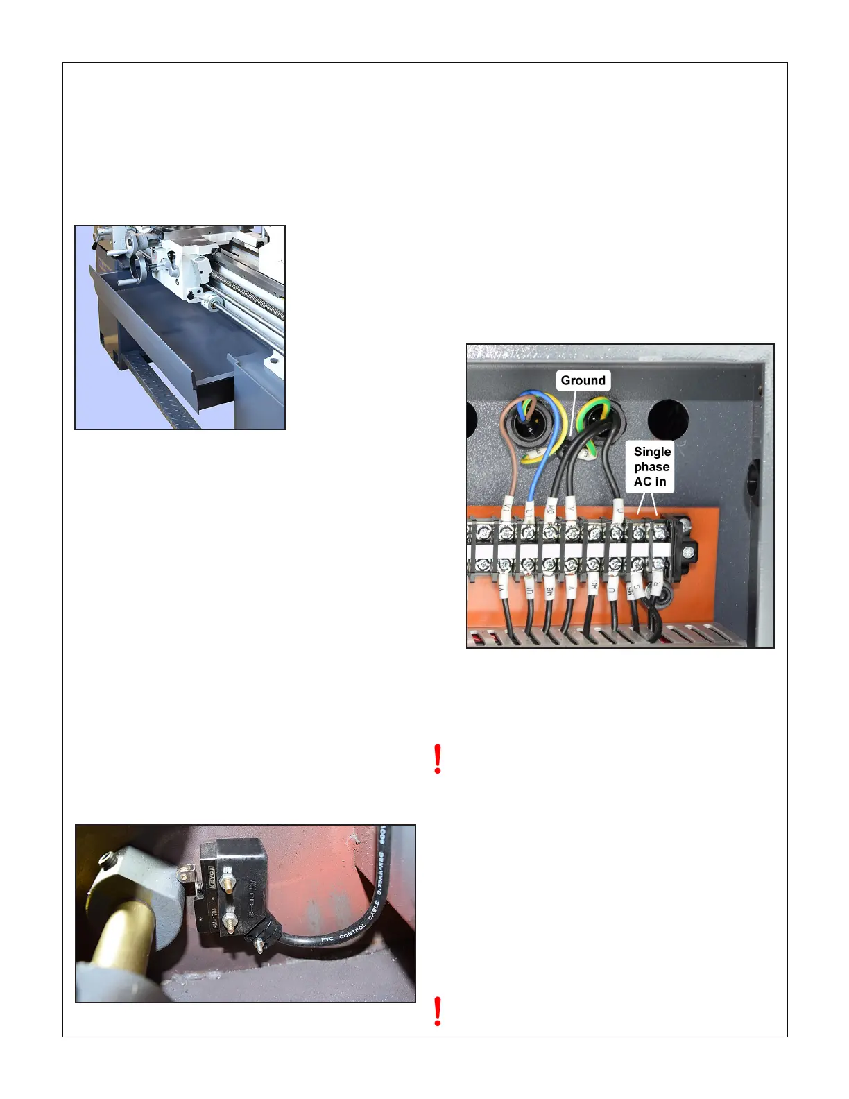
Remove the rear cover from the Left Hand cabinet (Headstock
Side). If the lathe did not come with a pre-installed power cord,
connect the right hand terminals, Figure 1-6, to the power
source using 12 AWG (minimum) 3-wire cord through a strain
relief bushing sized for the electrical box ports. For a single
phase installation, connect the power lines to terminals R and
S. For three-phase connection, there will be a T terminal in
addition to R and S, other wise it's the same, see Section 5
for more detail. Any power connection must be made by a li-
censed electrician, following all applicable codes.
INITIAL CHECKS
Read Section 3 if unsure about any item in the following
BEFORE connecting power, do the following:
1. Visually check the entire machine for possible distur-
bance in shipping, including the motor, Vee belts and
external gears under the belt cover left of the headstock.
Replace the belt cover.
2. Check oil level (sight glasses) in the headstock, the
saddle feed gearbox, and the apron. See Section 4.
3. If a chuck or faceplate is installed, check tightness of the
six Camlocks on the spindle nose, Section 3.
4. Set the speed selector gear levers to the lowest spin-
dle speed, 50 rpm. Make sure the gears are properly
meshed by "jiggling while shifting" — rotate the chuck
back and forth by hand while moving the levers into
position. Make certain that the motor control lever is set
to OFF, mid-travel, Figure 1-7.
Figure 1-4
Slide-out chip tray
LEVELING
Make sure the lathe is in its permanent location. The following
procedure ensures that the lathe bed is in the same state as it
was when the lathe was checked for accuracy in manufacture
— level from end to end along the bed, and from front to back.
In other words, no warping.
Make sure all leveling mounts and/or shims are properly
weight bearing, rmly in contact with the oor. Check and ad-
just level from end to end using a precision machinist’s level, if
available. If not, use the most reliable level on hand. Check and
adjust level front-to-back across the bed using a matched pair
of spacer blocks to clear the Vee tenons on the bed ways. The
blocks need to be at least 1/4 inch thick, ground or otherwise
accurately dimensioned. Alternatively, check for level on the
ground surface of the cross-slide as the carriage is traversed
from end to end. See also "Aligning the Lathe" in Section 4.
FOOTBRAKE & BELT COVER INTERLOCKS
The lathe will not run if the footbrake switch fails to close when
the foot treadle is released (brake OFF). This switch is locat-
ed inside the LH stand cabinet. Check that the D-shape cam
operates the switch when the treadle is pressed, Figure 1-5.
Do not change speed when the motor is running.
CLEANUP
Metal surfaces may have been protected by thick grease and/
or paper. Carefully remove these using a plastic paint scraper,
disposable rags and a light-oil such as WD-40.
CHIP TRAY
Check that the chip tray, Figure 1-4, can be pulled forward
without snagging coolant hoses and worklight wiring. Use ca-
ble ties if necessary.
Figure 1-5 Footbrake interlock switches
Figure 1-6 220 Vac input
 Loading...


