5
Copyright © 2020 Quality Machine Tools, LLCPM-1440GT v9 2020-10
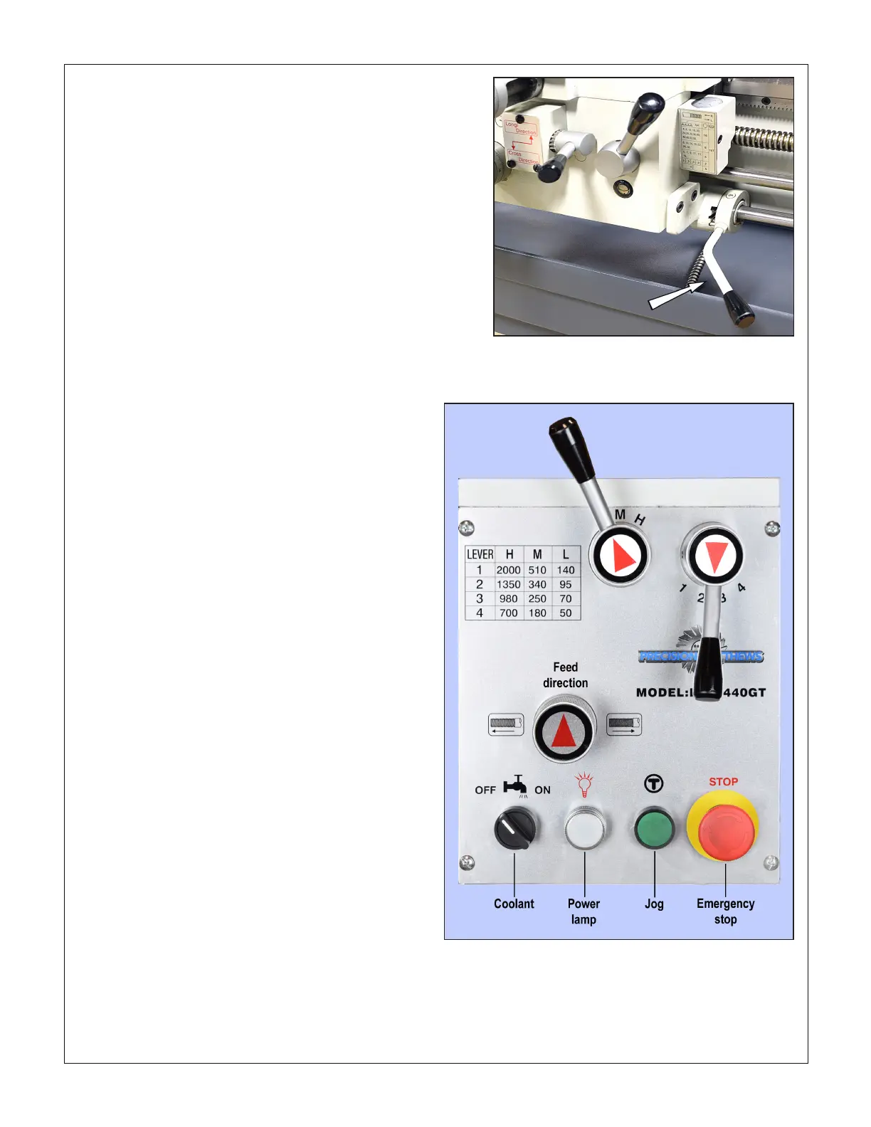
Figure 1-7 Motor control lever
Mid-travel OFF, DOWN Forward, UP Reverse
Figure 1-8 Front panel controls
The Feed Direction knob is shown here in the neutral con-
dition (no feed), leadscrew and feed shaft disengaged.
5. Set the Feed Direction knob to its center (neutral)
position, Figure 1-8.
6. Check that there are no clamps or locks on moving parts.
7. Check that the footbrake treadle is released (UP).
8. Set the saddle and cross-slide to approximate mid-travel.
9. Connect and switch on 220 Vac power. The power lamp,
Figure 1-8, should light, unless a circuit breaker in the
electrical box has tripped.
10. Be sure the Emergency Stop (E-Stop) button has not
been pushed in (it should pop out when twisted clock-
wise).
11. Shift the motor control lever DOWN. The spindle should
turn Forward, counter clockwise, viewed at the chuck
(nose) end. The control system can be rewired for
DOWN = Reverse, see the electrical diagram, Section 5.
12. Check the emergency function by pressing the E-Stop
button. The motor should stop. If this doesn’t happen,
the E-stop function is defective, and needs attention.
13. Reset (twist) the E-Stop button to restore power.
14. Check that the footbrake stops the motor.
15. Return the motor control lever to OFF, mid-travel.
16. Shift the motor control lever UP. The spindle should
Reverse, clockwise rotation, viewed at the chuck (nose)
end. The control system can be rewired for UP = For-
ward, see the electrical diagram, Section 5.
OPTIONAL TEST RUN PROCEDURE
Run the spindle for a few minutes, forward and reverse, at a
selection of the available 12 speeds.
If desired, the saddle feed gearbox may also be run at this
time, but rst make certain that all components aected have
been lubricated, then exercise the saddle and cross-slide
manually before power-feeding — see Section 3 for power
feed directions.
Precision Matthews recommends draining and relling all
three gearboxes (Headstock, Saddle Feed and Apron) af-
ter approximately 20 hours of initial run time. Lubricants
are specied in Section 4.
ALIGNING THE LATHE
The most important attribute of a properly set up lathe is its
ability to “machine parallel”, to cut a cylinder of uniform diame-
ter over its entire length. In other words, no taper.
Leveling of the lathe is a part of this, see earlier in this section.
Equally important is the alignment of the center-to-center axis
with the lathe bed, as seen from above. [Vertical alignment is
nowhere near as critical, rarely causing taper unless the lathe
is damaged or badly worn.] For more information see the nal
pages of Section 4, Servicing the Lathe.
 Loading...


