24
Copyright © 2020 Quality Machine Tools, LLCPM-1440GT v9 2020-10
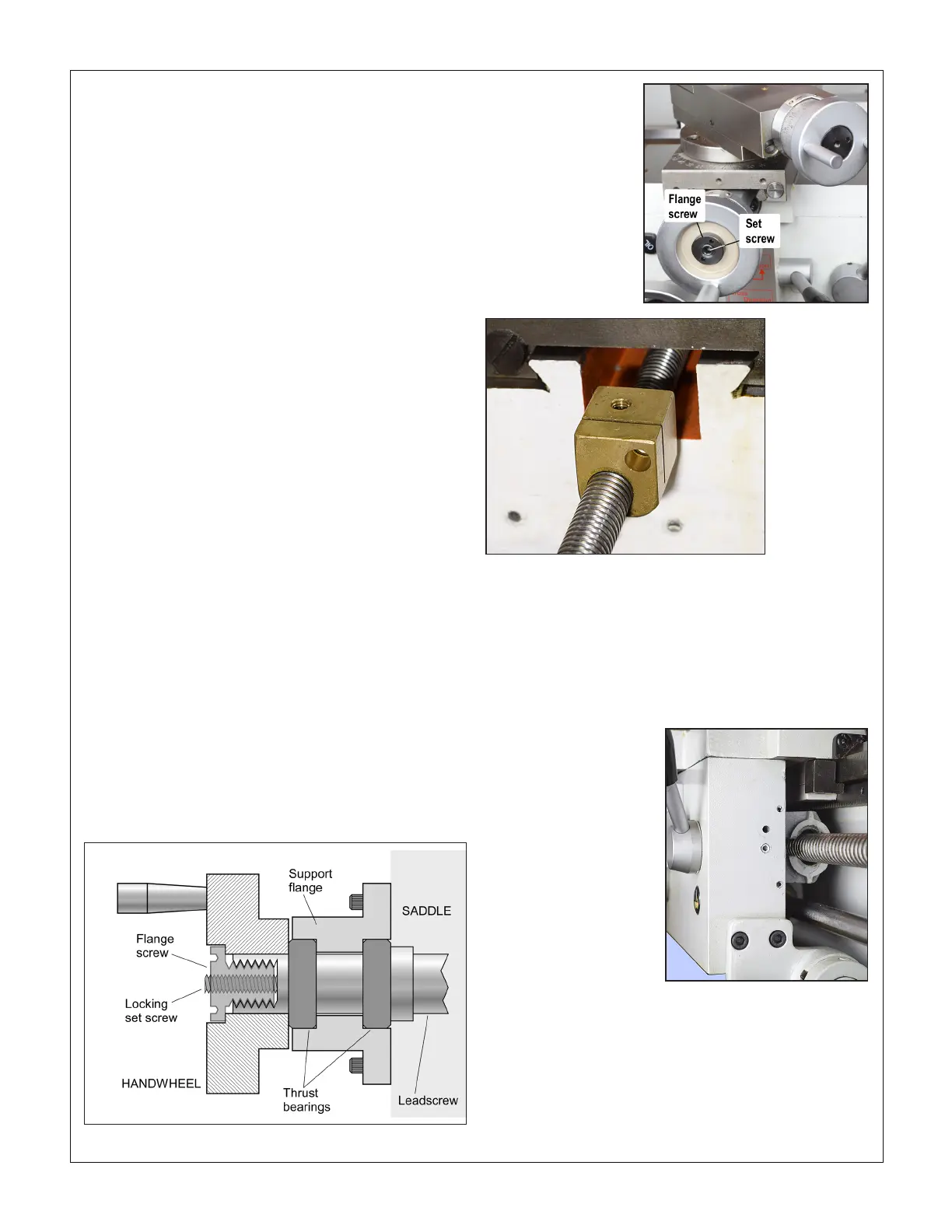
Figure 4-14 Cross-slide leadscrew nut (representative)
CROSS-SLIDE & COMPOUND BACKLASH
When alternating between clockwise and counter clockwise
rotation, the cross-slide handwheel may move freely a few de-
grees but the cross-slide table stays put. There may also be
similar lost motion in the compound. The acceptable amount
depends on the user, but 0.005” is generally a good compro-
mise. Smaller numbers are possible, but overdoing it can lead
to premature wear of leadscrew and nut.
Lost motion is due to two factors: 1. End-oat (in/out move-
ment of the handwheel) caused by insuciently tight coupling
of the leadscrew and thrust bearings. 2. Wear in the leadscrew
nut.
Factor #1 is correctable in both the cross-slide and compound.
Leadscrew handwheels on the PM-1440GT — cross-slide,
compound and tailstock — are attached in a similar way, Fig-
ure 4-13. The handwheel is locked to the leadscrew shaft by
a key (not shown). It is held in place by a ange screw in a
threaded well at the outer end of the leadscrew shaft. An in-
ternal locking set screw, bottomed in the well, prevents loos-
ening of the ange screw. To correct backlash due to loose
coupling between leadscrew and thrust bearings, back out the
set screw a turn or two, then tighten the ange screw using
a pin vise or needle-nose pliers. Do not tighten to the point
where the thrust bearings are over-compressed, resulting in
uneven motion. Back o for smooth rotation, with no appre-
ciable end-oat. Re-tighten the set screw. This tends to back
out the handwheel a small amount, so check end-oat again.
Factor #2 is correctable in the cross-slide by compressing
the leadscrew nut, Figure 4-14. Remove the compound from
the cross-slide, then remove the socket head screw secur-
ing the cross-slide to the leadscrew nut. Turn the cross-slide
handwheel clockwise to drive the nut backward until it can be
worked on at the back. Insert an M6 x 1 socket head screw, ap-
proximately 15 mm long, then tighten the screw as necessary.
Don't overdo this — a 45 degree turn of the screw represents
a backlash take-up of about 0.005".
The compound leadscrew nut is not adjustable.
SPLIT NUT ADJUSTMENT
In thread-cutting operations, if the split nut becomes exces-
sively loose — appreciable side to side movement — this may
be corrected by adjusting the gib at the right side of the apron.
Remove the threading dial, then tighten the two gib screws
as necessary, Figure 4-15. Overtightening can make disen-
gagement of the split nut dicult.
Figure 4-15 Split nut gib screws
TAILSTOCK CLAMP LEVER
The angular position of the clamp lever is adjustable. Slide
the tailstock toward the headstock to expose the threaded
stop screw at the right hand end of the bed. Remove the stop
screw, then very carefully slide the tailstock to the right, just
far enough to allow access to the hex nut below the tailstock
bed plate. Tighten the nut as necessary to achieve sold locking
with the lever near-vertical.
Figure 4-13A Handwheel attachment schematic
Figure 4-13B Handwheel
attachment

 Loading...

