12
Copyright © 2020 Quality Machine Tools, LLCPM-1440GT v9 2020-10
TAILSTOCK
The tailstock leadscrew has a 10 TPI thread, with 4 inch travel.
Inch and metric graduated collars on the tailstock handwheel
read 0.001” and 0.02 mm per division. A transverse slot at the
narrow end of the internal taper (MT3) provides clearance for
drills and other devices with tang ends. To remove tooling from
the tailstock taper turn the handwheel counter-clockwise (han-
dle end view) until resistance is felt, then turn the handle a little
more to eject the tool. Conversely, to install a taper tool make
certain that the quill is out far enough to allow rm seating.
For taper turning the tailstock may be oset by adjusting set
screws on either side, Figure 3-10. To move the tailstock to
the front, for instance, the screw on the lever side would be
unscrewed, then the opposing set screw would be screwed in
to move the upper assembly. Clamp screws hold the tailstock
rmly against a transverse rib in the base casting. Loosen
them if necessary to allow osetting.
A visual indication of the oset is provided by a scale on the
back surface, but this is not a reliable measure for precise
work. In practice, the only way to determine the oset precisely
is to "cut and try' on the workpiece, or scrap stock, homing in
on the correct degree of oset in small increments.
The same issues arise when re-establishing "true zero" of the
tailstock, in other words returning it to the normal axis for rou-
tine operations. One way to avoid cut-and-try is to prepare in
advance a bar of (say) 1" diameter quality ground stock, with
precise center drillings at both ends (do this by indicating for
zero TIR in a 4-jaw chuck, not in a 3-jaw unless known to be
predictably accurate). The prepared bar can then be installed
between centers and indicated along its length.
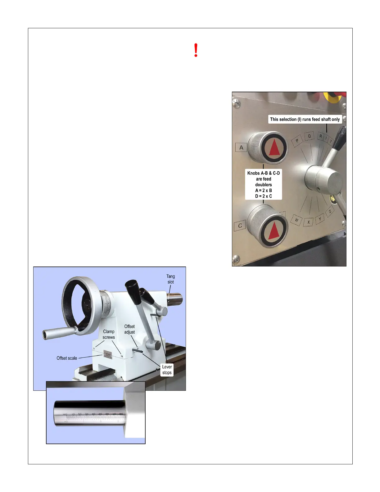
Figure 3-10 Tailstock
SADDLE FEED GEARBOX
Stop the motor before changing feed direction or rate
The saddle feed can be to the left, right, or disengaged, as
selected by the Saddle Feed knob on the main control panel,
Figure 3-1.
Figure 3-11 Saddle feed gearbox controls
ENGAGING THE POWER FEED
To activate the feed shaft set the upper lever on the gearbox,
Figure 3-11, to LETTER 'I' (selections P-Q-R-T are used only
for thread cutting).
The power feed lever on the apron, Figure 3-12, is active only
when the feed shaft is rotating (the split-nut lever engages
the leadscrew, and is typically used only for thread cutting).
When engaging power feed, move the lever gently, feeling
for the gears to mesh as you go. If the gears don’t engage at
the rst try, use the appropriate handwheel to jog the saddle
or cross-slide, whichever one you wish to move under power.
The split-nut lever — used for thread cutting — cannot be
engaged unless the power feed lever is NEUTRAL, neither
up or down.
The rate of power feed relative to spindle speed is set by the
lower lever on the gearbox, W-X-Y-Z, together with the "speed
doubler" knobs A-B and C-D. Feed rates are listed on the fol-
lowing page.

 Loading...

