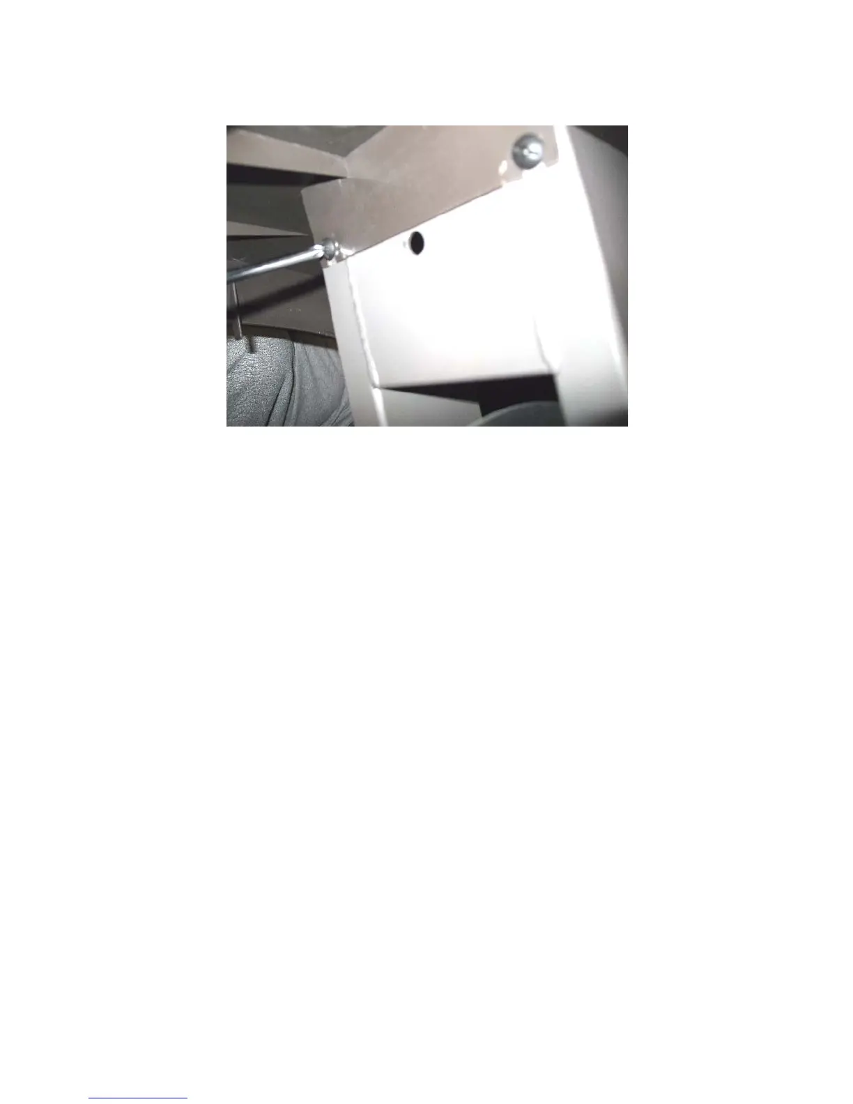
Diagram 7.1 - Top Cover Section Mounting
Bottom Cover Section
12. Remove the A.C. power cord from the A.C. input module.
13. Remove the two screws that fasten the input module to the bottom cover section.
14. Remove four screws, two front and two rear, that fasten the bottom cover to the frame.
15. Remove the bottom cover section.
Rear Cover Installation
Bottom Cover Section
16. Set the bottom cover section on its mounting position.
17. Fasten the bottom cover section with the screws removed in step 14.
18. Set the A.C. input module in its mounting position and fasten it with the screws removed in
step 13.
19. Plug the A.C. power cord into the A.C. input module.
Front Cover Section
20. Set the front cover section in its mounting position and snap it into the bottom cover section.
21. Fasten it with the screw loosened in step 10.
22. Set the lower PCA in its mounting position and fasten it with the screws removed in step 9.
Note: the screw in the bottom left hand corner of the lower PCA is also the frame ground.