EasyManua.ls Logo

Precor EFX 5.33 Service Manual

Precor EFX 5.33
94 pages
To Next Page IconTo Next Page
Page #1 background imageLoading...
Page #1 background image
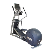
5.33 Elliptical Fitness Crosstrainer
Page 1
5.33 Elliptical Fitness Crosstrainer
Warning: This service manual is for use by Precor trained service providers only.
If you are not a Precor Trained Servicer, you must not attempt to service any Precor Product;
Call your dealer for service.
This document contains information required to perform the majority of troubleshooting, and
replacement procedures required to repair and maintain this product.
This document contains general product information, software diagnostic procedures (when
available), preventative maintenance procedures, inspection and adjustment procedures,
troubleshooting procedures, replacement procedures and electrical block and wiring diagrams.
To move directly to a procedure, click the appropriate procedure in the bookmark section to the
left of this page. You may “drag” the separator bar between this page and the bookmark section
to change the size of the page being viewed.
© 2004 Precor Incorporated
Unauthorized Reproduction and Distribution Prohibited By Law
20039-126

Table of Contents

Question and Answer IconNeed help?

Do you have a question about the Precor EFX 5.33 and is the answer not in the manual?

Precor EFX 5.33 Specifications

General IconGeneral
TypeElliptical Trainer
Resistance Levels20
Weight Capacity350 lbs
DisplayLCD
Programs12
PowerSelf-powered
Heart Rate MonitoringTouch and Telemetry

Summary

Section One - Things You Should Know

Right, Left, Front, and Back Conventions

Defines directional terms used from the user's perspective on the EFX 5.33.

Warning and Caution Statements and General Safety Guidelines

Highlights critical safety warnings and precautions for operating and servicing the EFX 5.33.

General Information

Provides contact information for dealer support and website resources.

Required Tools and Equipment

Tools, Equipment, Supplies, and Spares

Lists essential tools, equipment, supplies, and spare parts needed for service.

Procedure 2.1 - Accessing the Diagnostic Program

Diagnostic Tests Overview

Details the sequence to access and run diagnostic tests: Display, Keyboard, Heart Rate, Brake.

Procedure 2.2 - Accessing the Information Display

Information Display Options

Explains how to access Odometer, Hour Meter, Software Version, and Error Log displays.

Procedure 2.3 - Accessing the Set User Parameters Display

Measurement Standards Selection

Guides setting measurement units to U.S. Standard (pounds/miles) or Metric (kg/km).

Procedure 2.4 - Documenting Software Problems

Information to Record for Software Issues

Specifies details like serial number, software version, and problem description for reporting.

Section Three - Preventive Maintenance

Owner's Preventive Maintenance Schedule

Daily and weekly cleaning tasks recommended for owners to maintain the EFX 5.33.

Service Technician's On-Site Maintenance Tasks

Key inspection and maintenance tasks for service technicians during service calls.

Section Four - Checking EFX 5.33 Operation

Operational Check Procedure Steps

Step-by-step guide for verifying EFX operation, including resistance and noise checks.

Procedure 5.1 - Measuring Eddy Current Magnet Resistance

Safety Precautions and Procedure Overview

Highlights safety warnings and outlines the steps for measuring magnet resistance.

Procedure 5.2 - Adjusting Belt Alignment and Tension

Belt Alignment Adjustment

Details how to adjust step up belt alignment using tension bolts.

Belt Tension Measurement and Correction

Explains using a belt gauge to measure and correct step up belt tension.

Step Up and Input Belt Tension Adjustment

Provides guidance for fine-tuning step up and input belt tension.

Procedure 5.3 - Drive Input Assembly Adjustments

Input Drive Assembly Axle Alignment

Steps for aligning the crankarm to frame weldment using pillow block nuts.

Axle to Axle Measurement and Alignment

Procedure for aligning the input drive axle to the step up pulley axle.

Eddy Current Magnet and Drive Belt Tracking

Guides centering the eddy current magnet and tracking drive belts.

Procedure 6.1 - Troubleshooting the Interconnect Cable

Interconnect Cable and Connector Troubleshooting

Steps to diagnose and replace faulty lower/upper interconnect cables or mid-point connectors.

Procedure 6.2 - Troubleshooting the Keypad and Upper PCA

Keypad and PCA Troubleshooting Steps

Diagnosing unresponsive keys or display issues by testing keypad and upper PCA.

Procedure 6.3 - Troubleshooting the Speed Sensor

Speed Sensor Circuit Description and Testing

Explains the speed sensor function and guides testing its operation and voltage output.

Procedure 6.4 - Troubleshooting the Eddy Current System

Eddy Current System Troubleshooting Steps

Diagnosing resistance issues by checking voltage, wiring, and magnet resistance.

Procedure 6.5 - Upper Display does not Illuminate

Display Illumination Troubleshooting

Steps for troubleshooting a non-illuminating display, including fuse checks and PCA voltage.

Procedure 7.1 - Replacing or Removing a Rear Cover Section

Cover Removal and Replacement Procedures

Detailed instructions for removing and reinstalling various cover sections of the EFX 5.33.

Procedure 7.2 - Replacing Display Enclosure or Upper PCA

Display Enclosure and Upper PCA Replacement

Guide for replacing the display housing front panel or the upper PCA component.

Procedure 7.3 - Replacing a Lower PCA

Lower PCA Replacement Steps

Instructions for removing and installing the lower PCA, considering different serial codes.

Procedure 7.4 - Replacing a Lower or Upper Interconnect Cable

Interconnect Cable Replacement

Procedure for replacing the interconnect cable between the lower and upper PCA.

Procedure 7.5 - Replacing a Power Entry Module

Power Entry Module Replacement Steps

Steps to replace the power entry module, including fuse checks and wire connections.

Procedure 7.6 - Replacing a Crankarm Assembly

Crankarm Assembly Replacement

Instructions for removing and installing crankarm assemblies, noting positioning.

Procedure 7.7 - Replacing a Pillow Block Bearing

Pillow Block Bearing Replacement

Guide for removing and replacing pillow block bearings on the drive weldment.

Procedure 7.8 - Replacing an Input Drive Assembly

Input Drive Assembly Replacement

Steps to remove and install the input drive assembly, including pulleys and disk.

Procedure 7.9 - Replacing an Input Pulley Belt

Input Pulley Belt Replacement

Detailed instructions for replacing the input pulley belt on the drive unit.

Procedure 7.10 - Replacing a Step-Up Pulley Belt

Step-Up Pulley Belt Replacement

Instructions for removing and installing the step-up pulley belt.

Procedure 7.11 - Replacing a Step-Up Pulley Assembly

Step-Up Pulley Assembly Replacement

Guide for replacing the entire step-up pulley assembly, including belts and bearings.

Procedure 7.12 - Replacing a Speed Sensor Assembly

Speed Sensor Assembly Replacement

Steps for replacing the speed sensor assembly and setting the correct gap.

Procedure 7.13 - Replacing an Eddy Current Magnet Assembly

Eddy Current Magnet Assembly Replacement

Instructions for removing and installing the eddy current magnet assembly.

Procedure 7.14 - Replacing a Stairarm Pivot Block

Stairarm Pivot Block Replacement

Guide for replacing the stairarm pivot block, checking crankarm pin condition.

Procedure 7.15 - Replacing a Wheel Assembly

Wheel Assembly Replacement

Steps for removing and installing wheel assemblies on the stairarm.

Procedure 7.16 - Replacing a Stairarm Pedal

Stairarm Pedal Replacement

Instructions for replacing the stairarm pedal and tightening mounting bolts.

Procedure 7.17 - Replacing a Stairarm

Stairarm Replacement Steps

Comprehensive guide for removing and installing a complete stairarm assembly.

Procedure 7.18 - Replacing a Ramp Assembly

Ramp Assembly Replacement

Detailed steps for removing and installing the ramp assembly and its components.

Procedure 7.19 - Replacing a Handlebar

Handlebar Replacement Steps

Instructions for removing and installing the handlebar assembly.

Procedure 7.20 - Replacing an Input Belt Tensioner

Input Belt Tensioner Replacement

Steps for replacing the input belt tensioner and adjusting belt tension.

Procedure 7.21 - Replacing an Upper Pivot

Upper Pivot Replacement

Guide for removing and installing the upper pivot component.

Procedure 7.22 - Replacing a Secondary Link

Secondary Link Replacement

Instructions for replacing the secondary link connecting handlebar and stairarm.

Procedure 7.23 - Replacing a Stairarm Connector

Stairarm Connector Replacement

Steps for removing and installing the stairarm connector.

Procedure 7.24 - Replacing a Main Column

Main Column Replacement

Detailed procedure for removing and installing the main column assembly.

Procedure 7.25 - Replacing a Frame Tube

Frame Tube Replacement

Instructions for removing and installing frame tubes.

Procedure 7.26 - Replacing a Ramp Support

Ramp Support Replacement

Guide for removing and installing the ramp support.

Procedure 7.27 - Replacing a Ramp Mounting Bracket

Ramp Mounting Bracket Replacement

Steps for removing and installing the ramp mounting bracket.

Procedure 7.28 - Replacing a Rear Cover Support

Rear Cover Support Replacement

Instructions for replacing the rear cover support, including wiring.

Procedure 7.29 - Replacing a Power Entry Module Fuse

Power Entry Module Fuse Replacement

Steps to replace fuses in the power entry module.

Procedure 7.30 - Replacing Handlebar to Stairarm Link

Handlebar to Stairarm Link Replacement

Guide for replacing the handlebar to stairarm link for specific serial codes.

Procedure 7.31 - Replacing the PROM

PROM Replacement Procedure

Instructions for safely replacing the Programmable Read-Only Memory (PROM).

Related product manuals