Procedure 7.4 - Replacing a Lower or Upper Data Cable
Procedure
Note: Before you install a new data cable, ensure that the data cable is defective. Refer to
Procedure 6.1. The upper data cable is connected to the upper PCA at the rear of the display,
and is then routed down the right outrigger tube. The upper data cable meets the lower data
cable at the bottom, front of the right outrigger tube. The upper data cable is connected to the
lower data cable via a coupler module. The lower data cable is routed through the frame from the
bottom of the right outrigger tube to the lower PCA.
1. Set the on/off switch in the “off” position, then unplug the power cord from the A.C. outlet.
Replacing an Upper Data Cable
2. Remove the three screws from the rear of the display assembly that fasten it to the upright
support.
3. Disconnect the data cable and heart rate cable from the rear of the display assembly.
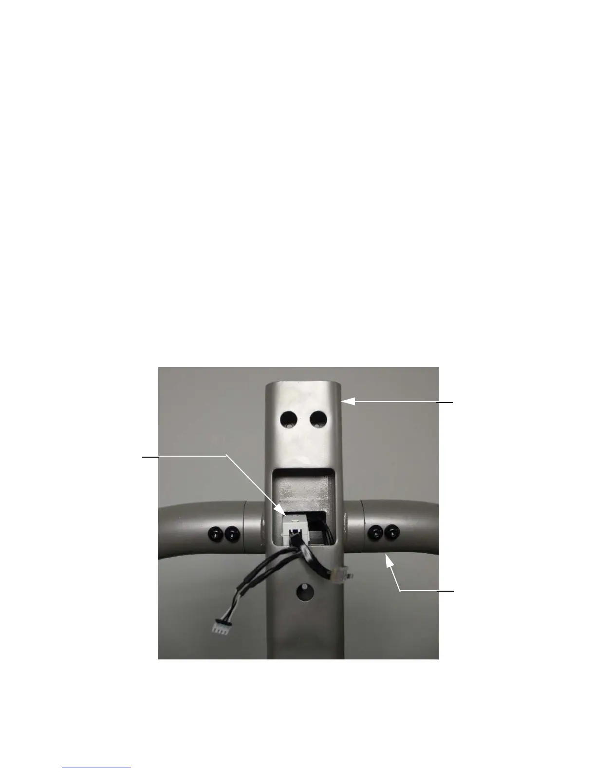
4. Unsnap and remove the ferrite from the data cable and heart rate cable. See Diagram 7.2.
Diagram 7.2 - Upright Support
5. Remove the three bolts that fasten the upper end of the right outrigger to the upright
support.
Ferrite
Upright Suppor