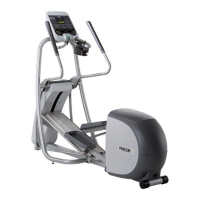
4. Position the right side upright support near the base
frame and route the data cable inside of the base side
cover and up through the right upright (Figure 3).
IMPORTANT DO NOT pinch or crush the cable during
assembly.
Figure 3
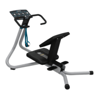
5. Position the right upright support onto the base frame
so that the side cover lip fits inside the upright
support and attach it using three screws and three
washers (Figure 4). Partially tighten the fasteners.
6. Repeat Steps 2 through 5 to attach the left upright
support.
Figure 4
NOTE If a personal viewing system (PVS) will be added, route the PVS and network cables
through the inside of the left upright support. Be careful not to pinch the cables.
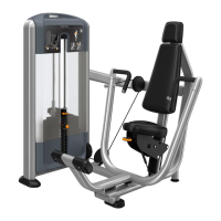
Attach the dash
1. With assistance, set the dash assembly on top of the upright
supports. NOTE The dash slips down into the uprights. Pull it
up slightly so that the screw holes line up correctly.
2. Attach the dash assembly to each upright using three screws
and three washers (Figure 5). Partially tighten the
screws.
Figure 5
3.
Tighten all 12 screws to 25 ft-lb (33.90 Nm) of torque.
Tighten the lower upright screws in the order shown in Figure
6.
Figure 6
Complete dash attachment
1. Remove the two screws from the back of the dash cover. Remove
the dash cover and set it aside with the screws.
2. Route the data cable through the right tube of the dash assembly,
up the back frame, and out through the top hole (Figure 7).
NOTE If you are attaching a PVS or networked console, route those
cables through the left side of the dash assembly at this time.
Figure 7
Attach heart rate bar
1. Position the heart rate bar assembly against the dash
frame and attach it using two screws and two
washers . Partially tighten the fasteners.
2. Route the heart rate cable up through the back frame and
out through the top hole (Figure 8).
Figure 8
3. Remove the screw from the bottom of the tread arm
(Figure 9).
4. Remove the bottom and front plastic covers from each
tread arm.
Figure 9
5. Fit the tread arm into the heart rate bar and against the
dash assembly. Attach it using two screws and two
washers (Figure 10). Use a hex key to partially tighten
the screws.
6. Attach the underside of each heart rate arm using one
screw . Fully tighten the fasteners (Figure 11).
Figure 10
7. Repeat Steps 3 through 6 to attach the other arm and
then tighten all six socket head screws to 25 ft-lb (33.90
Nm) of torque.
NOTE To install a touchscreen console, continue with the next
section. To install a non-touchscreen console, skip to Attach
the treadmill hood.
Figure 11
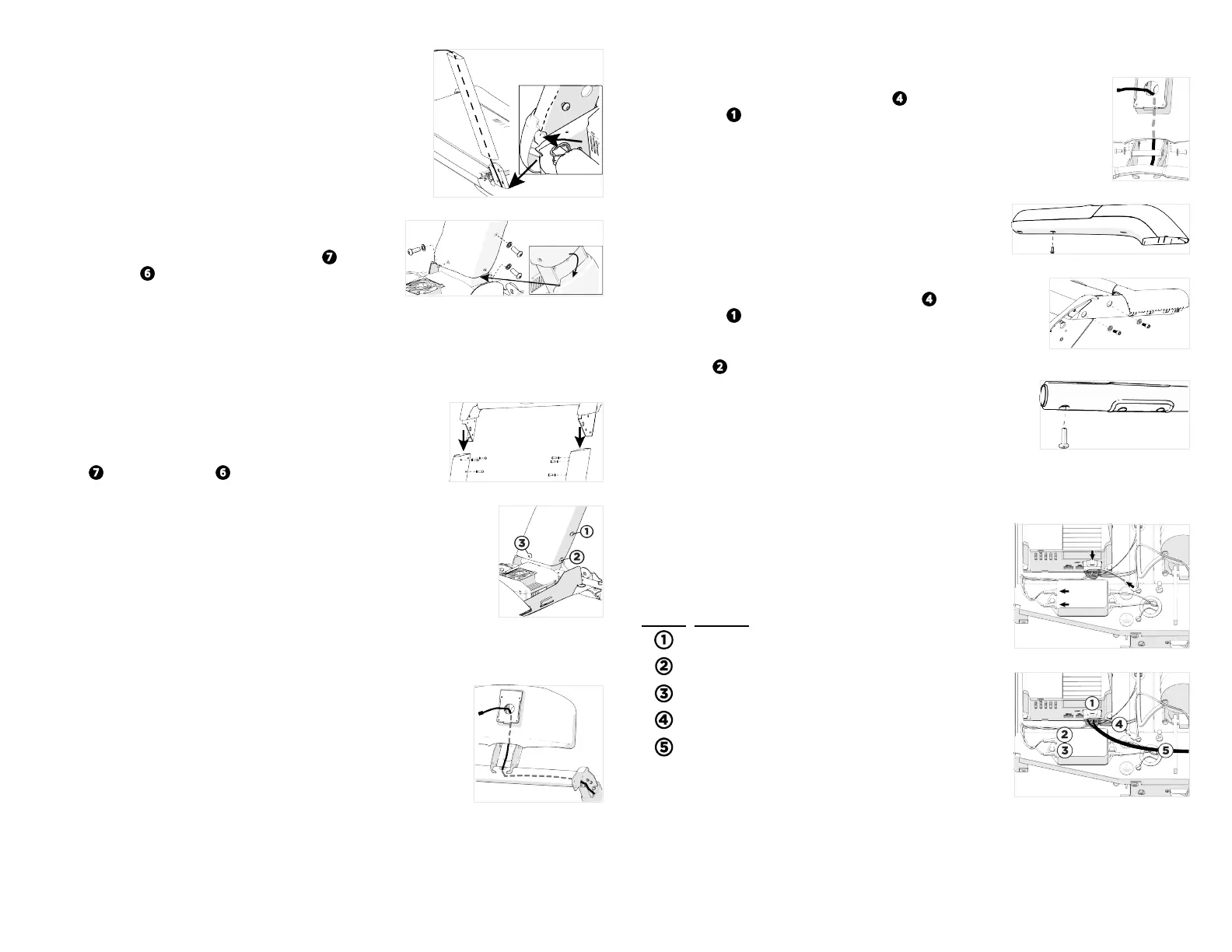
Attach filter to drive power cable
1. Disconnect the existing power cable from the drive unit,
power filter, and ground terminal. Completely remove it
from the treadmill (Figure 12).
2. Connect the new power cable according to Figure 13 and
Table 1.
Position Connector
Drive input connectors
Brown lead with quick-connect terminal
Blue lead with quick-connect terminal
Green and yellow lead with quick-connect terminal
AC input cable to the power cable
Figure 12
Figure 13
3. Use the Velcro fasteners to attach the power supply on the right side of the treadmill base.
Plug the AC input cable into the socket on the power supply.
©2020 Precor Incorporated |Treadmill 600-700 Assembly Guide | P/N 305285-101C | 23 October 2020| 2