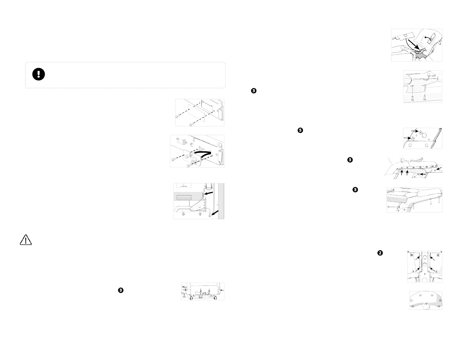
4. Route the DC output cable through the cable ties behind the power supply, toward the
upright support on your right. Bend the cable ties over the DC output cable to hold it in
place. NOTE Bundle the excess cable and secure it under the cable clips.
5. Connect the black AC power cable on the AC wiring harness to the socket on the power
supply.
Install accessory jack
IMPORTANT The touchscreen console includes an accessory jack panel that you
must install on the treadmill. The panel connects the TV and Ethernet cables to
the facility’s network.
For touchscreen consoles only:
1. Remove the screws securing the blank plate at the right-front
corner of the treadmill (Figure 14). Discard the blank plate.
Figure 14
2. Thread the cable assembly down through the channel in the
upright support on your right (Figure 15). Drape excess cable
over the inside edge of the support and tape into place, if neces-
sary.
3. Pass the lower end of the TV cable through the right-hand
grommet, and insert it into the connector inside the panel. Use
a 7/16-inch torque wrench to tighten the connectors to 30 in-lb
(3.39 Nm) of torque.
Figure 15
4. Pass the lower end of the Ethernet cable through the right-
hand grommet and snap it into the eight-pin coupler in the
panel (Figure 16).
5. Fit the lower ends of any optional console cables into the notch
in the upper edge of the panel.
6. Replace the panel and fully tighten the corresponding screws.
Figure 16
WARNING Before you finish assembling the treadmill base, examine the electrical
bleed line between the belt motor and the frame. Make sure the bleed line is con-
nected securely to both the motor and the frame as shown in the following figure, and
verify that it is not damaged. DO NOT connect the treadmill to electrical power while
the hood is removed.
Attach treadmill hood
1. Place the hood onto the treadmill. Using a #3 Phillips head
screwdriver, attach it using four screws (Figure 17). Fully tighten
the fasteners.
Figure 17
Attach safety key
1. Fit the bottom part of the safety key assembly onto the bottom
of the dash assembly and heart rate arms. NOTE Flex the plastic
to snap it into place.
2. Position the top piece of the safety key assembly on top of the
bottom part (Figure 18).
Figure 18
3. Route the cable under the black bar on the safety key assembly
and up through the dash (Figure 19).
4. Attach the top part of the safety key assembly using two screws
.
Figure 19
Attach dash arm
1.
Insert two grommets into of the dash arms, just above
each upright support (Figure 20).
Figure 20
2.
Attach the front arm cover using four screws (Figure 21).
Figure 21
3.
Attach the bottom arm cover using four screws (Figure
22).
4. Repeat Steps 1 to 3 to attach the covers to the other arm.
Figure 22
Install console
To attach a console, refer to the installation instructions shipped with your console. Once you have
attached all the cables, follow the steps below to complete assembly of your treadmill.
1.
Secure the console to the dash assembly using four screws (Figure
23).
Figure 23
2. Place the dash cover onto the back of the dash assembly and attach it
using the two screws previously removed plus five screws from the hard-
ware kit (Figure 24).
Figure 24
©2020 Precor Incorporated |Treadmill 600-700 Assembly Guide | P/N 305285-101C | 23 October 2020| 3
 Loading...