Do you have a question about the Precor 600 Line and is the answer not in the manual?
Position and attach base side cover using screws.
Route data cable and attach right upright support with screws.
Attach left upright support with screws and washers.
Attach heart rate bar assembly to dash frame using screws and washers.
Route heart rate cable through back frame and out top hole.
Attach tread arms to heart rate bar using screws and washers.
Set dash assembly on upright supports and align screw holes.
Attach dash assembly to each upright with screws and washers.
Remove dash cover, route data cable, and reattach cover.
Disconnect existing power cable from drive unit and ground terminal.
Connect new power cable and attach power supply with Velcro fasteners.
Remove blank plate and thread cable assembly down through upright.
Pass TV and Ethernet cables through grommet and into panel connectors.
Fit bottom safety key onto dash assembly and position top piece.
Route safety key cable and attach top part with screws.
Insert grommets into dash arms above each upright support.
Attach front and bottom arm covers using screws.
Place hood onto treadmill and attach using screws.
Secure console to dash assembly using screws.
Place dash cover onto dash assembly and attach with screws.
Use wrench to loosen jam nuts on rear feet and adjust for level.
Plug power cord into an appropriate outlet.
Turn on treadmill, set speed, and observe belt centering.
Start treadmill, set speed, and adjust tracking with roller bolt.
Increase speed and make small adjustments as needed.
Verify that the STOP button pauses and stops the workout.
Verify that the reset switch stops the treadmill and resets console.
Verify treadmill stops automatically after inactivity.
Enable safety code setting for unauthorized use prevention.
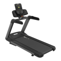
The Precor Treadmill 600/700 Line is a piece of cardio equipment designed for walking, jogging, and running workouts. This assembly guide provides instructions for setting up and maintaining the treadmill, ensuring safe and proper operation.
The treadmill requires assembly, and Precor strongly recommends that at least two people perform the installation to prevent injury. The equipment should be assembled on a solid, flat, and level surface, close to its intended use location. A minimum clearance of 6 meters (23.6 inches) on either side and 2 meters (79 inches) behind the treadmill is required. The equipment should not be moved without assistance once assembled.
The assembly process involves various fasteners, including washers, self-tapping pan head screws, socket head cap screws, plastic grommets, star tooth washers, and button head screws. A hardware kit is provided, and extra hardware may be included. Required tools include:
Specific torque measurements are provided for critical fasteners to ensure proper assembly and safety:
| Brand | Precor |
|---|---|
| Model | 600 Line |
| Category | Fitness Equipment |
| Language | English |