C960 Series Commercial Treadmill
Page 29
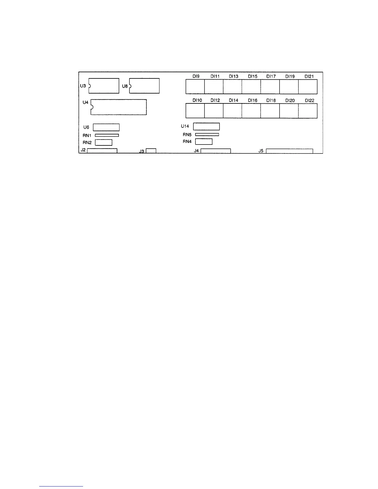
Diagram 5.2 - Upper PCA Component Layout
Table 5.1 - Voltage Test Points (Function Keys Not Pressed)
PLACE THE POSITIVE LEAD OF THE THE VOLTMETER SHOULD
VOLTMETER ON... READ...
Pin 1 of J4 5 Vdc ± 500 mVdc
Pin 2 of J4 5 Vdc ± 500 mVdc
Pin 3 of J4 5 Vdc ± 500 mVdc
Pin 4 of J4 5 Vdc ± 500 mVdc
Pin 6 of J4 5 Vdc ± 500 mVdc
Pin 7 of J4 5 Vdc ± 500 mVdc
Pin 8 of J4 5 Vdc ± 500 mVdc
Pin 9 of J4 5 Vdc ± 500 mVdc
Pin 4 of J2 5 Vdc ± 500 mVdc
Pin 5 of J2 5 Vdc ± 500 mVdc
Pin 6 of J2 5 Vdc ± 500 mVdc
Table 5.2 - Voltage Test Points (Function Keys Pressed)
Place the positive lead At the electronic The voltmeter
of the voltmeter on... console, press... should read between...
Pin 1 of J4 Left CHANGE key 0 Vdc and 350 mVdc
Pin 2 of J4 STOP key 0 Vdc and 350 mVdc
Pin 3 of J4 SPEED
T key 0 Vdc and 350 mVdc
Pin 4 of J4 SPEED
S key 0 Vdc and 350 mVdc
Pin 6 of J4 QUICK START key 0 Vdc and 350 mVdc
Pin 7 of J4 ENTER key 0 Vdc and 350 mVdc
Pin 8 of J4 Right CHANGE key 0 Vdc and 350 mVdc
Pin 9 of J4 Center CHANGE key 0 Vdc and 350 mVdc
Pin 4 of J2 RESET key 0 Vdc and 350 mVdc
Pin 6 of J2 INCLINE
T key 0 Vdc and 350 mVdc
Pin 7 of J2 INCLINE
S Tkey 0 Vdc and 350 mVdc