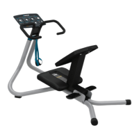
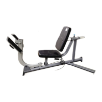
Attach foot plate to movement arm
Figure 3
1. With assistance, align the foot plate to the mounting bracket on the movement arm. Have
your assistant hold the foot plate to the mounting bracket on the movement arm, while you
attach the foot plate using:
4 – M10 x 30 mm flat head cap screws
4 – 11 mm flat washers
4 – M10 nylon lock nuts
2. Attach the handlebar assembly to the seat frame using:
2 – M10 x 130 mm hex head bolts (horizontally)
2 – M10 x 75 mm flat head cap screws (vertically)
6 – 11 mm flat washers
4 – M10 nylon lock nuts
3. Attach the seat pad base support to the seat frame using:
2 – M10 x 25 mm flat head cap screws
2 – 11 mm flat washers
2 – M10 nylon lock nuts
Install weight stack tower
Figure 4
1. Insert the guide rods into the holes at the bottom of the weight tower frame.
Important: A hole passes through one end of each guide rod. Be sure to insert the end
without the hole into the bottom of the frame.
2. Pull the guide rods away from the frame, keeping their lower ends engaged in the bottom of
the tower frame. Slide one weight stack bumper over each guide rod, narrow end up.
3. Check the guide rods for silicone lubricant. If you do not find any, add some of the lubricant
supplied in the hardware kit to the guide rods.
4. Carefully slide eighteen 15 lb. (7 kg) weight plates onto the guide rods, one by one.
5. Slide the top weight plate (25 lb/12 kg) with weight stack stem onto the two guide rods and
lower the stem through the center holes of the weight plates.
6. Slide the ring at the end of the tether on the weight selection pin over the right-hand post on
the top weight plate.
7. Screw the weight stack cable loosely into the center post on the top weight plate.
8. Secure the weight stack assembly to the weight tower frame. Slide an O-ring onto the smaller
diameter shoulder of each guide rod locking collar, then slide the collars onto the guide rods
(the smaller diameter shoulder on the collar should be facing up). Re-align the guide rods with
the mounting holes at the top of the weight tower.
9. Have your assistant hold the guide rods in place. Slide the collars up until the shoulder of
each collar fits into the tower frame. Insert one M6 × 45 mm button head cap screw through
the holes in each collar and each guide rod, then attach an M6 nylon lock nut to each button
head cap screw. Tighten the button head cap screws securely, then attach and tighten the M8
set screws using the S4 hex key.
10. Spray a lint-free cloth with isopropyl alcohol and wipe the front of the weight plates clean.
Use a second lint-free cloth to remove any remaining alcohol before applying labels.
11. Apply the weight plate labels (select LBs or KGs) to the right of the weight selection holes.
©2021 Precor Incorporated | VSL Leg Press/Calf Extension| Assembly Guide | P/N CWR107777-102 ENU 31 July 2021 | 2

 Loading...