20 www.pridemobility.com Jazzy 1113
IV. DISASSEMBLY
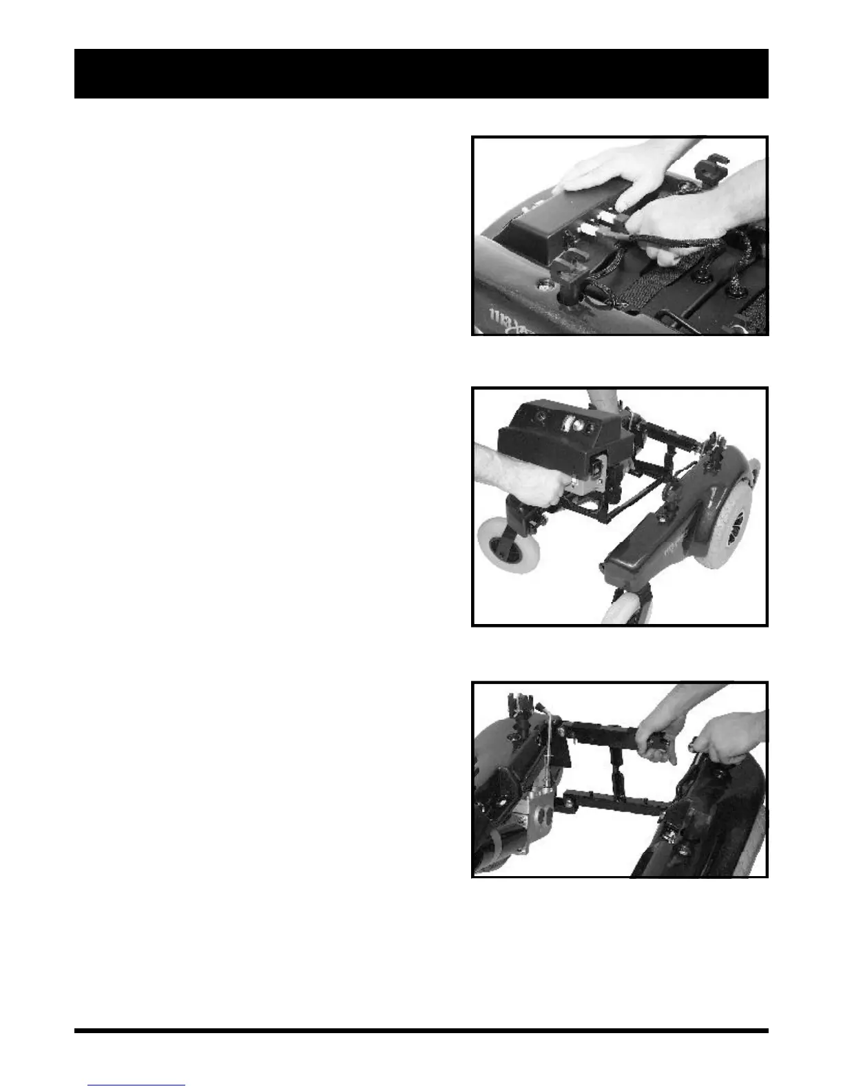
6. Squeeze together the latch release levers that hang
vertically down from the crossbar at the rear of the battery
well frame. See figure 17. Lift up the rear end of the battery
well frame. Pull it to the rear of the chair to release the
front slots from the locating pins on the bottom bar of the
front frame.
To disassemble the right frame assembly from
the front frame:
1. Remove the battery well frame.
2. Stand behind the unit and grasp the right frame assembly
handle (located next to the front seat post) with your right
hand.
3. Use your left hand and thumb to hold the front frame and
press and hold (toward the center of the front frame) the
silver-colored latch release lever. See figure 18.
4. Push the right frame assembly outward (toward the right)
with your right hand holding the right frame assembly
handle.
5. Pull up with your left hand on the front frame until the
latching mechanism releases.
6. Keep pulling upward with your left hand until the locating
pin on the bottom of that side of the front frame releases
from its slot in the right frame assembly.
7. Carefully let the right frame assembly tilt to a resting
position.
To disassemble the left frame assembly from the
front frame:
1. Remove the battery well frame.
2. Stand behind the unit and grasp the left frame assembly
handle (located next to the front seat post tower) with
your left hand.
3. Use your right hand and thumb to hold the front frame
and press and hold (toward the center of the front frame)
the silver-colored latch release lever. See figure 18.
4. Push the left frame assembly outward (toward the left)
with your left hand holding the left frame assembly handle.
5. Pull up with your right hand on the front frame until the
latching mechanism releases.
6. Keep pulling upward with your right hand until the locating
pin on the bottom of that side of the front frame releases
from its slot in the left frame assembly.
7. Carefully let the left frame assembly tilt to a resting position.
Figure 18. Side Frame Removal
Figure 17. Battery Well Removal
Figure 16. Disconnect Battery Boxes