24 www.pridemobility.com Jazzy 1113
V . COMFORT ADJUSTMENTS
Anti-tip Wheels
The anti-tip wheels are designed to give your power chair increased stability on rough surfaces. The anti-tip wheels
are preset at the factory for smooth surfaces or indoor use only. If you plan on using your power chair on rough
surfaces, it may be necessary to adjust the anti-tip wheels to better suit your needs. The anti-tip wheels may need
adjustment if the following occur:
n When coming to a stop your power chair tips forward excessively.
n The anti-tip wheels constantly rub the ground.
WARNING! Consult your authorised Pride Provider before attempting to change the anti-
tip wheel height! Changing the anti-tip wheel height affects handling under deceleration!
WARNING! The higher you raise the anti-tip wheels, the more you increase your power
chair’s tendency to tilt forward when coming to a stop. You can compensate for this by
having your authorised Pride Provider make a small adjustment to the pre-programmed
deceleration setting in the controller or by moving the seat assembly farther to the rear of
your power chair.
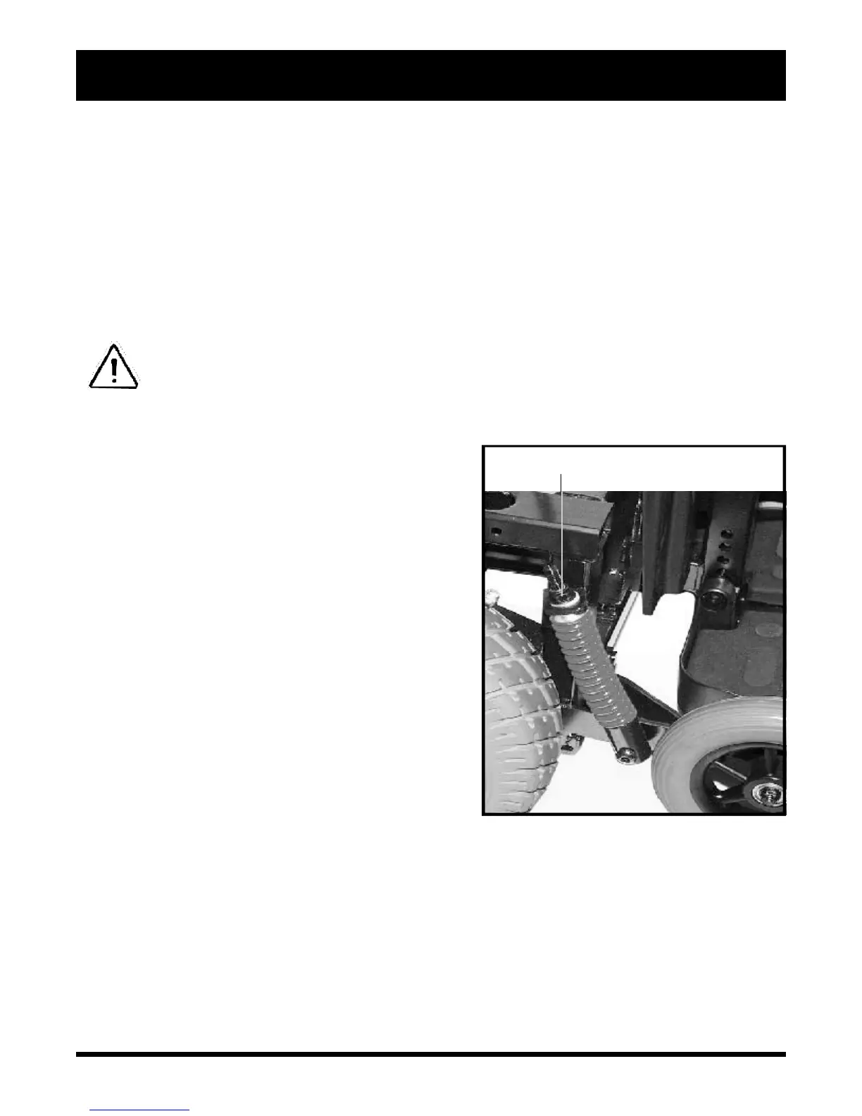
Figure 24. Anti-Tip Adjustment
ANTI-TIP ADJUSTMENT NUT
To adjust the anti-tip wheels:
1. Make sure that the manual freewheel levers are in the
drive position.
2. Unplug the controller connector(s) from the electronics tray.
3. Remove the seat. See IV. “Disassembly.”
4. Unplug the left and right motor connectors.
5. Unplug and remove both battery boxes.
6. Remove all four seat post ball detent pins and remove the
seat posts.
7. Remove both left and right shrouds by loosening and
removing the hardware located on the top of the body
shroud near the seat post holes.
8. Locate the anti-tip adjustment nut. See figure 24.
9. Turn the adjustment nut anticlockwise to lower the anti-
tip wheels and soften the suspension. Turn the adjustment
nut clockwise to raise the anti-tip wheels and stiffen the
suspension. Make the same adjustment on both anti-tip
wheels.
10. Reinstall the left and right shrouds.
11. Reinstall the four seat posts.
12. Reinstall both battery boxes.
13. Plug the left and right motor connector(s) back into their
sockets.
14. Reinstall the seat.
15. Plug the controller connectors into the electronics tray.