Do you have a question about the Printronix P7000 Series and is the answer not in the manual?
Introduces the P7000 printers, PSA3 architecture, controller boards, and features.
Guidance on ordering correct spare parts for P7000 printers.
Explains how to identify a P7000 printer model based on its alphanumeric code.
Details H-Series models for specific regions and their unique platens/shuttles.
Explains HD printers using Windows drivers and LQ1600K emulation for high-res output.
Describes ZTP printers' special hardware/software for seamless form ejection.
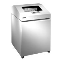
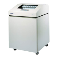
Details paper handling for pedestal and cabinet models.
Explains the meaning of WARNING, CAUTION, IMPORTANT, and NOTE headings.
Provides a systematic approach to maintenance tasks and understanding the manual.
Explains how control panel keys, messages, and key combinations are highlighted.
German safety notices regarding maintenance, cleaning, and handling.
Details the function of each electrical control and indicator on the printer.
Explains the function of various mechanical controls for paper handling and alignment.
Outlines safety standards and requirements for the printer's power cord.
Details specifications for interface cables to comply with EMC regulations.
Contact information for ordering genuine Printronix supplies.
Importance and necessity of periodic cleaning for printer life and reliability.
Step-by-step instructions for cleaning the printer's exterior surfaces.
Detailed steps for cleaning the shuttle frame assembly and its components.
Procedures for cleaning the card cage fan assembly and surrounding areas.
Lists fault messages and general symptoms for troubleshooting printer malfunctions.
Lists aids within the manual to help isolate printer malfunctions.
Provides a table of P7000 ASCII (Spool) error messages with explanations and solutions.
Lists printer problems not indicated by LCD messages with troubleshooting procedures.
Lists common causes and solutions for communication problems across interfaces.
Provides steps and LCD results for selecting and running diagnostic tests.
Steps to access the boot diagnostics menu by holding specific keys while powering on.
Describes two methods for exiting the boot diagnostics menu.
Instructions for accessing the Factory menu by holding specific keys.
Instructions for exiting the Factory menu by pressing the ON LINE key.
Explains accessing the Exception Menu for fault-specific troubleshooting information.
Step-by-step instructions on how to generate a hex dump for troubleshooting.
Explains a software reset that clears memory and loads power-up configuration.
Describes a hard reset as power shutdown and restart, running initialization and diagnostics.
Outlines the need for occasional adjustments and tests as part of maintenance.
Lists various adjustment and test procedures with corresponding page numbers.
Instructions for loading program files using the Firmware Download Utility.
Instructions for loading software via the parallel port using DOS commands.
Steps for loading software through the parallel port using a three-key sequence.
Instructions for loading software through the Ethernet NIC.
Procedures for reprogramming the security key using an SPX module.
Procedure to check cables for shorts to ground.
Procedure to check cables for pin-to-pin shorts.
Explains the chapter covers removal/installation procedures for field-replaceable units (FRUs).
General warnings and important notes regarding component replacement.
Lists component replacement procedures with corresponding page numbers.
Details removal of V5 and V6 controller boards, with safety precautions.
Instructions for installing the controller board, including software download.
Procedure for installing version 2 hammer spring assemblies using a short tip tool.
Procedures for removing memory modules and the security key.
Procedures for installing memory modules and the security key.
Procedures for removing the NIC from V5 controller boards.
Procedures for installing the NIC on V5 controller boards.
Detailed procedures for removing the platen.
Procedures for installing the platen and related components.
Procedures for removing terminating resistor packs from the V5 controller board.
Procedures for installing resistor packs in the V5 controller board.
Procedures for removing resistor packs from the V6 controller board.
Procedures for installing resistor packs in the V6 controller board.
Procedures for removing the splined shaft.
Procedures for installing the splined shaft.
Procedures for removing the shuttle frame assembly.
Procedures for installing the shuttle frame assembly.
Procedures for removing the tractors.
Procedures for installing the tractors.
Procedures for removing the tractor assembly support gates.
Procedures for installing the tractor assembly support gates.
Explains the chapter contains drawings of electrical and mechanical assemblies.
Lists illustrations of printer components with corresponding page numbers.
Explains how line matrix printers create characters and graphics using dot patterns.
Details printer speed metrics (lpm, cpm, ipm) and factors affecting them.
Describes the three integrated subassemblies of the line matrix printing mechanism.
Describes the hammer bank assembly and hammer spring counts.
Details hammer springs and hammer bank components, including magnetic attraction.
Details how ribbon ink consumption is displayed and managed.
Defines options within the ZTP SETTINGS menu.
Explains setting the ribbon life tracking based on print density.
Defines default and alternative ribbon end point actions.
Describes how the printer identifies ribbons and logs depleted ribbons.
Explains user interaction via the control panel keys and LCD.
Lists the responsibilities of the Data Controller (DC).
Lists the responsibilities of the Engine Controller (EC).
Identifies the MPC8245 microprocessor as the DC unit's processor.
Explains flash memory storage for code, its characteristics, and capacity.
Explains System SDRAM usage for program variables and buffers.
Describes NVRAM for storing configuration and statistical data.
Explains how the V8 ASIC handles addresses and chip selects.
Specifies V8 support for SDRAM banks.
Specifies V8 support for flash memory banks.
Describes DMA channels for direct memory access.
Details the V8's handling of the control panel interface.
Explains "Dot Plucking" as a DMA function controlled by the EC.
Lists the I/O functions controlled by the V8 ASIC.
Describes support circuitry for serial and parallel interfaces.
Describes the 80C167 microcontroller and its role as the EC.
Details the 80C167 bus configuration for address, data, and operation.
Explains the 80C167 chip's power reduction modes: idle and Energy Star.
Describes the EC's local flash memory for boot code, program code, and tables.
Explains the MECA ASIC's role in controlling printer motor functions.
Details analog drive circuits for motors and hammers, and sensor monitoring.
Details AC voltage input tolerance and overvoltage protection.
Explains the two DC power supply systems (+5V for logic, +48V/+8.5V for motors/hammers).
Introduces VGL and PGL programming languages for creating forms, bar codes, and graphics.
Provides a block diagram of the printer's interconnection of subsystems.
Illustrates cable routing for cabinet models.
Illustrates cable routing for pedestal models.
Provides tables for testing continuity and shorts in main wire harness components.
Details pinouts for V5 and V6 controller boards.
Provides a schematic for power supplies used in specific P7X00 models.
Provides a schematic for power supplies used in specific P7X00 models.
Provides a schematic for power supplies used in specific P7000 models.
Provides a schematic for the CT board, including Twinax and Coax connections.
Provides a schematic for the SureStak Power Stacker PCBA, showing motors and sensors.
Details the Centronics I/O cable assembly specifications and important notes.
Provides a diagram and pinout for the Centronics-to-Dataproducts adapter cable.
Provides a schematic and resistance chart for the Twinax Auto-Termination cable.
Illustrates the Smart-T cable extension.
Illustrates a 2-pin jumper cable assembly.
Illustrates the AC input power supply cable assembly.
Illustrates the AC power input cable assembly.
Illustrates the PS I/O cable assembly and its applicability.
Illustrates the cable assembly for the card cage fan.
Illustrates the cable assembly for the control panel.
Illustrates the cable assembly for the exhaust fan.
Illustrates the cable assembly for the hammer bank logic.
Illustrates the hammer bank power cable assembly and its usage.
Illustrates the dual hammer bank power cable assembly for the P7220 printer.
Illustrates the cable assembly for the Magnetic Pickup Unit (MPU).
Illustrates the cable assembly for the ribbon guide.
Illustrates the extension cable assembly for the ribbon motor.
Illustrates the cable assembly for the shuttle motor drive.
Provides a wiring diagram for the power stacker frame cable.
Illustrates the logic cable for the power stacker.
Illustrates the power cable for the power stacker.
Provides a wiring diagram for the power stacker rail cable.
Illustrates the elevator I/O cable assembly for the power stacker.
Illustrates the cable assembly for the hammer bank fan.
Illustrates the MPU assembly and its wire table.
Illustrates the paper detector switch assembly and its wire table.
Illustrates the platen interlock switch assembly and its wire table.
Introduces the SureStak Power Stacker as an option for printers.
Describes the mechanical operation of the power stacker.
Instructions for setting up the power stacker.
Steps for loading paper and starting the power stacker.
Lists common stacker problems and refers to troubleshooting.
Initial inspection steps for the power stacker.
Procedures to verify proper connection and operation of stacker components.
Checks stacker motors and cables.
Procedures for removing the power stacker assembly.
Procedures for installing the power stacker assembly.
Procedures for replacing the constant force spring.
Procedures for removing and replacing the timing belts.
Procedures for replacing the roller drive shaft.
Refers to illustrations and part lists for the power stacker.
Provides an overview of the ZTP printer's capabilities.
Covers ZTP printer operation, including paper loading and setup.
Instructions for loading paper and setting up tractors on the ZTP printer.
Instructions for removing paper from the ZTP printer.
Procedures for adjusting the paper guide leaves.
Instructions for positioning the paper out sensor for optimal performance.
Procedure to set the tear bar distance for proper form ejection.
Procedure to set the top-of-form position for accurate printing.
Defines options within the ZTP SETTINGS menu.
Lists specified continuous form paper types and their ranges.
Lists procedures for ZTP printer adjustments and tests.
Steps to prepare the ZTP printer for maintenance.
Steps to return the ZTP printer to normal operation.
Procedures for removing and installing the barrier panel.
Procedures for adjusting the paper feed timing belt.
Procedures for adjusting paper guide leaves.
Procedure for adjusting the paper out sensor.
Procedure for adjusting horizontal paper tension.
Lists component replacement procedures with corresponding page numbers.
Procedures for replacing the paper feed timing belt.
Procedures for replacing the control panel assembly.
Procedures for replacing the top cover assembly.
Procedures for replacing the paper feed motor.
Procedures for replacing the paper guide leaf, center.
Procedures for replacing the paper guide leaf, front.
Procedures for replacing the paper guide leaf, outer.
Procedure for adjusting the paper out sensor.
Procedures for replacing the splined shaft.
Procedures for replacing the support shaft.
Procedures for replacing the left/right tractors.
Procedures for replacing the tractor assembly support gate.
Divides the appendix into paper specifications and form design sections.
Describes minimum paper specifications for best printer performance.
Advises on proper storage conditions for forms.
Lists the three kinds of continuous form paper specified for use.
Specifies the recommended form weight range.
Specifies the maximum form thickness allowed.
Specifies maximum acceptable evenness variation.
Refers to specifications for tractor pin engagement.
Provides definitions for terms related to continuous form paper.
Recommends paper conformity to specifications for best printer performance.
Advises on using fillers in cartons to protect paper during handling.
Guidelines for storing cartons to prevent paper damage.
Advises on protecting paper from temperature and humidity extremes for stabilization.
Provides details for early P5000 single hammer bank printers.
Provides details for later P5000 single hammer bank printers.
Provides details for P5000 PSA3 single hammer bank printers.
Provides details for P5220D and P5224D dual hammer bank printers.
Information required before calling Printronix Customer Support.
Contact information for ordering genuine Printronix supplies.
| Print Technology | Line Matrix |
|---|---|
| Resolution | 180 x 144 DPI |
| Connectivity | Ethernet, Parallel, Serial |
| Paper Handling | Fanfold paper |
| Noise Level | 55 dBA (depending on model) |
| Dimensions | Varies by model |
| Weight | Varies by model |