GP4000 Series Hardware Manual
73
Specifications of Serial Interface COM1
Introduction
NOTE: For instructions on how to connect to other devices, always refer to the “GP-
Pro EX Device/PLC Connection Manual”.
The serial port is not isolated. The SG (signal ground) and FG (frame ground)
terminals are connected inside the GP unit.
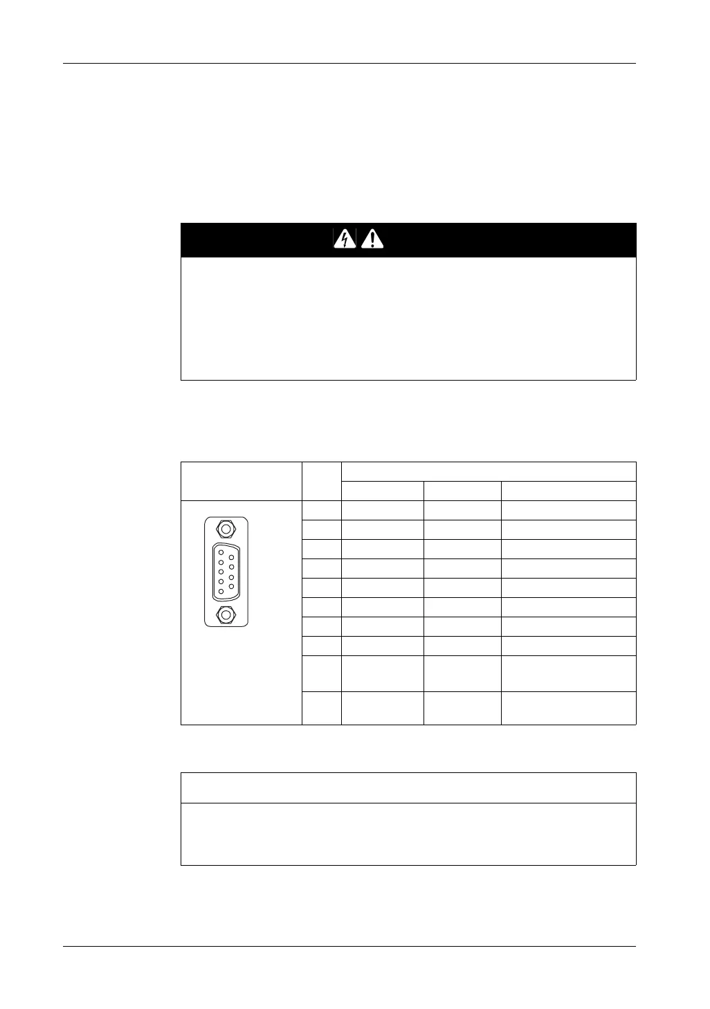
Serial Interface COM1
GP-4301T / GP-4301TW / GP-4303T: D-Sub 9 pin plug connector via an RS-232C
cable.
NOTE:
*1
You can switch pin #9 between RI and VCC via software.
Interfit bracket is #4-40 (UNC).
DANGER
ELECTRIC SHOCK
When using the SG terminal to connect an external device to the panel:
z Verify that a short-circuit loop is not created when you set up the system.
z Connect the #5 SG terminal to remote equipment when the host (PLC) unit is
not isolated. Connect the #5 SG terminal to a known reliable ground connection
to reduce the risk of damaging the circuit.
Failure to follow these instructions will result in death or serious injury.
Pin Connection Pin
No.
RS-232C
Signal Name Direction Meaning
1 CD Input Carrier Detect
2 RD(RXD) Input Receive Data
3 SD(TXD) Output Send Data
4 ER(DTR) Output Data Terminal Ready
5 SG - Signal Ground
6 DR(DSR) Input Data Set Ready
7 RS(RTS) Output Request to Send
8 CS(CTS) Input Send possible
9 CI(RI)/VCC Input/– Called Status Display
+5V±5% Output 0.25A
*1
Shell FG – Frame Ground (Common
with SG)
NOTICE
EQUIPMENT DAMAGE
Use only the rated current.
Failure to follow these instructions can result in equipment damage.
9
6
5
1
(GP unit side)