7
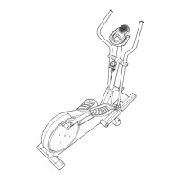
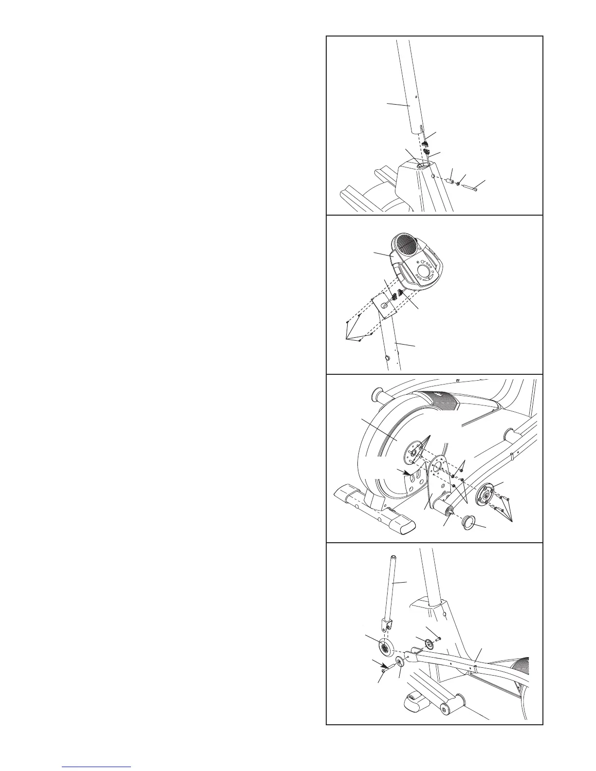
5. While another person holds the Upright (2) in the posi-
tion shown, connect the Upper Wire Harness (86) to
t
he Lower Wire Harness (87). C
arefully pull the
upper end of the Upper Wire Harness to remove
a
ny slack. While holding the Upper Wire Harness,
insert the Upright into the Frame (1). Do not pinch
the Wire Harnesses.
Slide an M10 Split Washer (70) and a Frame Spacer
(83) onto an M10 x 87mm Button Screw (63). Insert
the Button Screw into the Frame (1) and the Upright
(2).
Make sure that the concave end of the Frame
Spacer is facing the Frame. Do not tighten the
Button Screw yet.
63
70
83
87
86
2
1
5
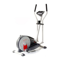
6. While another person holds the Console (5) in the
position shown, connect the wire harness on the
Console to the Upper Wire Harness (86). Insert the
excess wire harness into the Upright (2).
Attach the Console (5) to the Upright (2) with four M4
x 16mm Screws (66).
Be careful to avoid pinching
the wire harnesses.
7
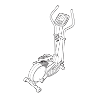
7. Slide the Right Crank Arm (48) onto the four indicated
welded bolts; make sure that the Right Crank Arm is
in the indicated cutout in the Pedal Disk (8). Next,
finger tighten four M8 Jamnuts (127) onto the welded
bolts. Then, fully tighten one of the Jamnuts, and then
tighten the Jamnut farthest from the first Jamnut. Then,
tighten the remaining two Jamnuts.
Attach a Hub Cover (116) to the Right Crank Arm (48)
with four M8 x 25mm Patch Screws (22). Then, tighten
an Adjustment Knob (16) onto the right Latch Pin (119).
6
5
66
86
Console
Wire Harness
2
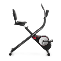
8. Apply a small amount of grease to the long side of a
Bolt Set (27). Hold a Handlebar Leg (79) and a Ramp
Wheel (29) inside of the bracket on the Left Pedal
Arm
(14). Insert the long side of the Bolt Set, with a Pedal
Arm Cap (38) on it, through the Left Pedal
Arm, the
Handlebar Leg, and the Ramp Wheel.
Tighten the short side of the Bolt Set (27), with a Pedal
Arm Cap (38) on it, into the long side of the Bolt Set.
Attach the other Handlebar Leg (not shown) and
Ramp Wheel (not shown) to the Right Pedal
Arm (not
shown) in the same way
.
8
79
29
27
27
38
38
14
M
ake sure the
w
ire harnesses
d
o not get
pinched and
damaged during
this step.
Make sure the
wire harnesses
do not get
pinched and
damaged during
this step.
Cutout
22
116
Welded
Bolts
48
127
127
16
119
8
Grease
 Loading...