20
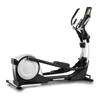
Look into the access opening and locate the Reed
Switch (58). Rotate the Pulley (66) until a Magnet (41)
is aligned with the Reed Switch. Note: For clarity, the
shields are shown removed in the drawing below.
Slightly loosen the two indicated M4 x 16mm Screws
(61). Slide the Reed Switch (58) slightly toward or
away from the Magnet (41). Then, retighten the
M4 x 16mm Screws.
Plug in the power adapter and rotate the pulley for a
moment. Repeat these actions until the console dis-
plays correct feedback.
When the reed switch is correctly adjusted, unplug
the power adapter and reattach the parts that you
removed. Then, plug in the power adapter.
HOW TO ADJUST THE DRIVE BELT
If the pedals slip while you are pedaling, even while the
resistance is adjusted to the highest setting, the drive
belt may need to be adjusted. To adjust the drive belt,
first unplug the power adapter.
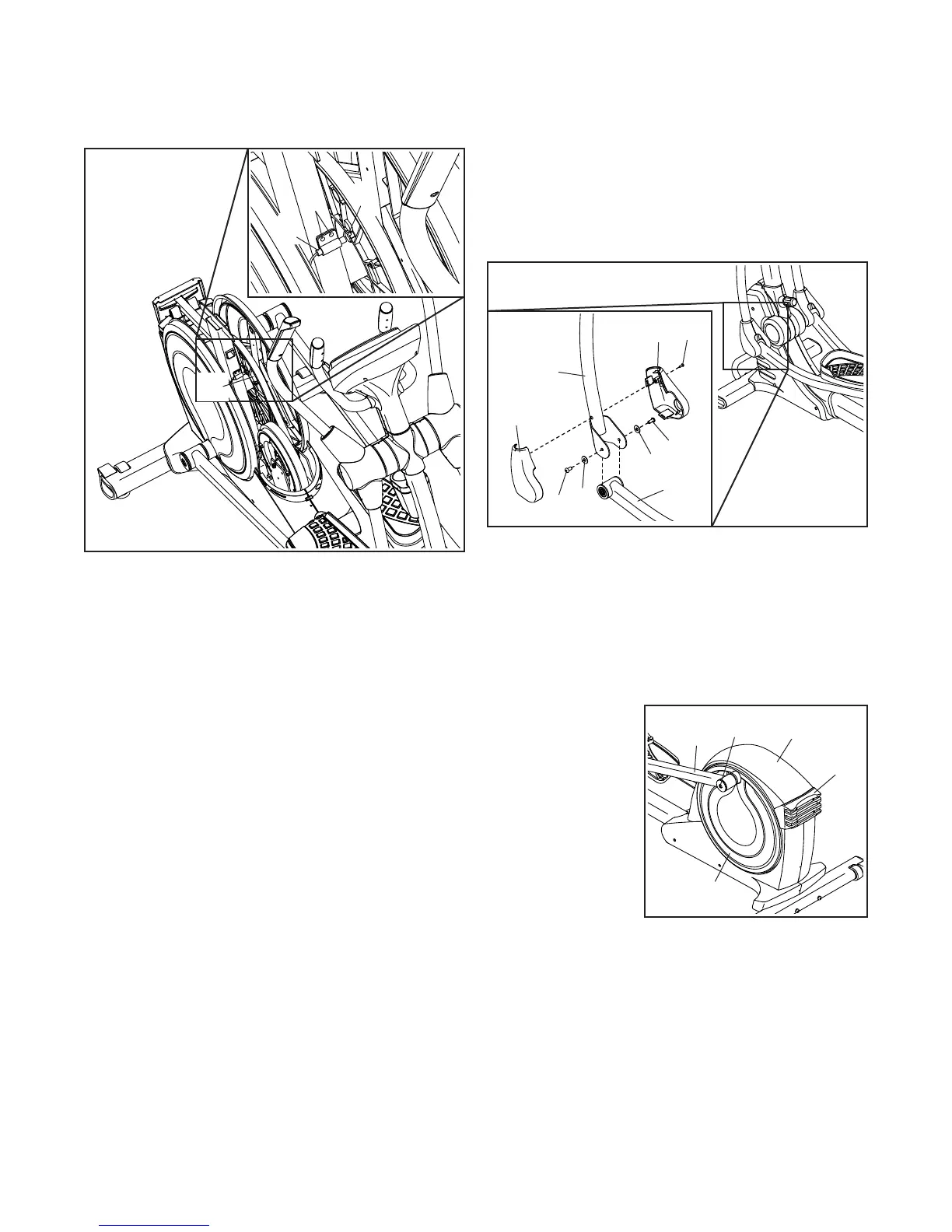
Next, remove the M4 x 16mm Screw (61) from the Left
Leg Inner Cover (39), and remove the Left Leg Inner
Cover and the Left Leg Outer Cover (92).
Then, remove the two M8 x 16mm Screws (76) and the
two M8 Washers (33) from the Left Upper Body Leg
(101) and the Left Pedal Arm (14).
Next, remove the M8 x 14mm Shoulder Screw (81)
from the Left Pedal Arm (14), and Remove the Left
Pedal Arm.
Next, remove the
four M4 x 16mm
Screws (not
shown) from the
Large Storage
Foot (27), and
remove the Large
Storage Foot.
Next, remove the
two M4 x 16mm
Screws (not
shown) from the
Top Shield (37),
and use a standard screwdriver to pry the Top Shield
upward off the elliptical. Then, pry the left Pedal Disc
(26) off the elliptical.
66
58
41
61
39
33
33
92
101
76
14
76
61
37
14
81
26
27
 Loading...