12
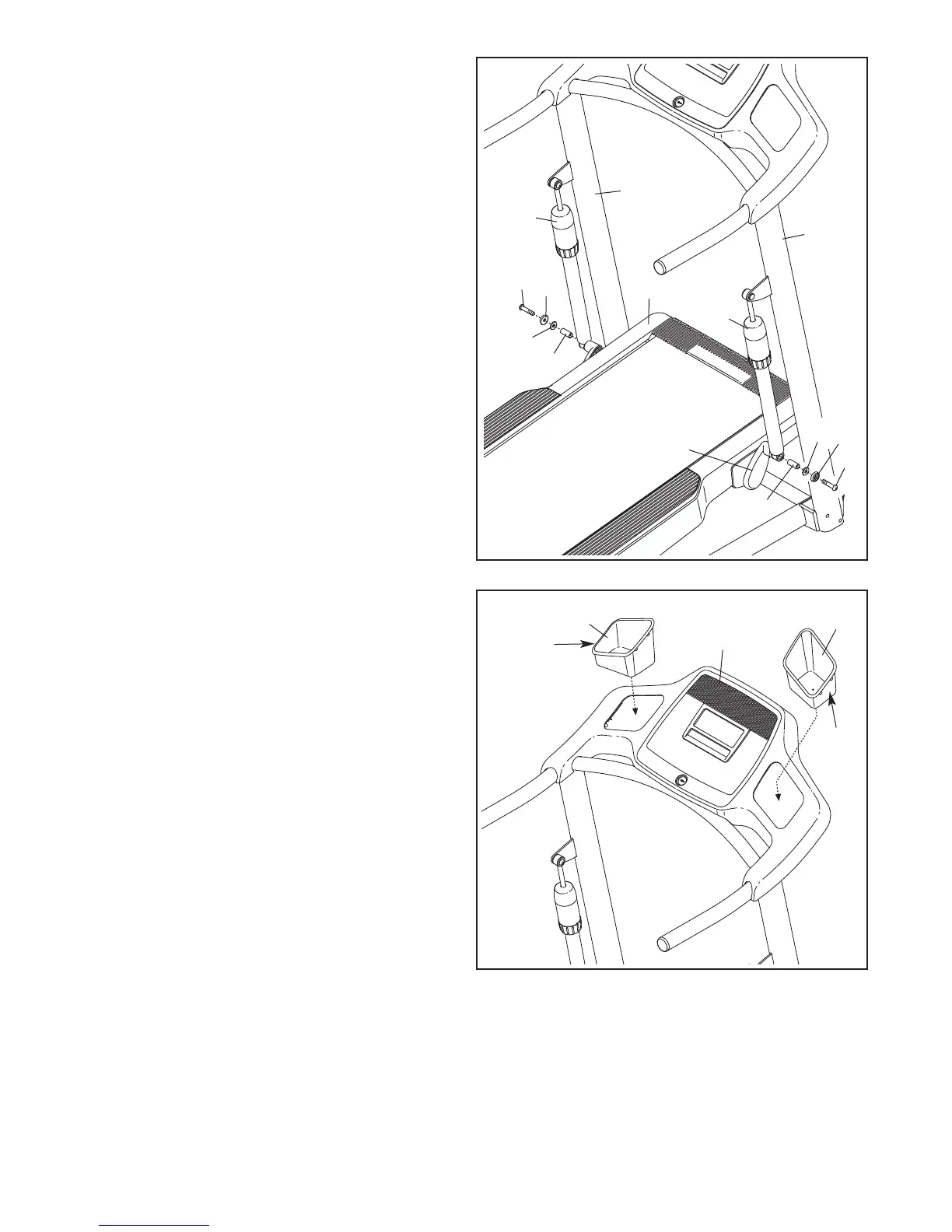
12. If necessary, press the Left and Right Accessory
Trays (81, 82) into the console assembly. Press
the indicated sides of the Accessory Trays
into the console assembly first.
12
81
82
Console
Assembly
13. Make sure that all parts are properly tightened before you use the treadmill. If there are sheets of clear
plastic on the treadmill decals, remove the plastic. To protect the floor or carpet, place a mat under the tread-
mill. Note: Extra hardware may be included. Keep the included hex keys in a secure place; one of the hex
keys is used to adjust the walking belt (see pages 21 and 22).
First
First
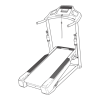
11. With the help of a second person, raise the
Frame (45) until the incline assembly is aligned
with the lower ends of the Shock Cylinders (69).
A
ttach the lower end of each Shock Cylinder
with a 3/8" x 2" Patch Bolt (3), a Lower Cylinder
C
ap (90), a 3/8" Washer (11), and a Cylinder
Spacer (70) as shown. Do not overtighten the
Patch Bolts.
Make sure that both Shock Cylinders (69) are
set at the same firmness level (see page 18).
3
90
11
70
3
90
69
69
64
72
45
Incline
Assembly
70
11
11