11
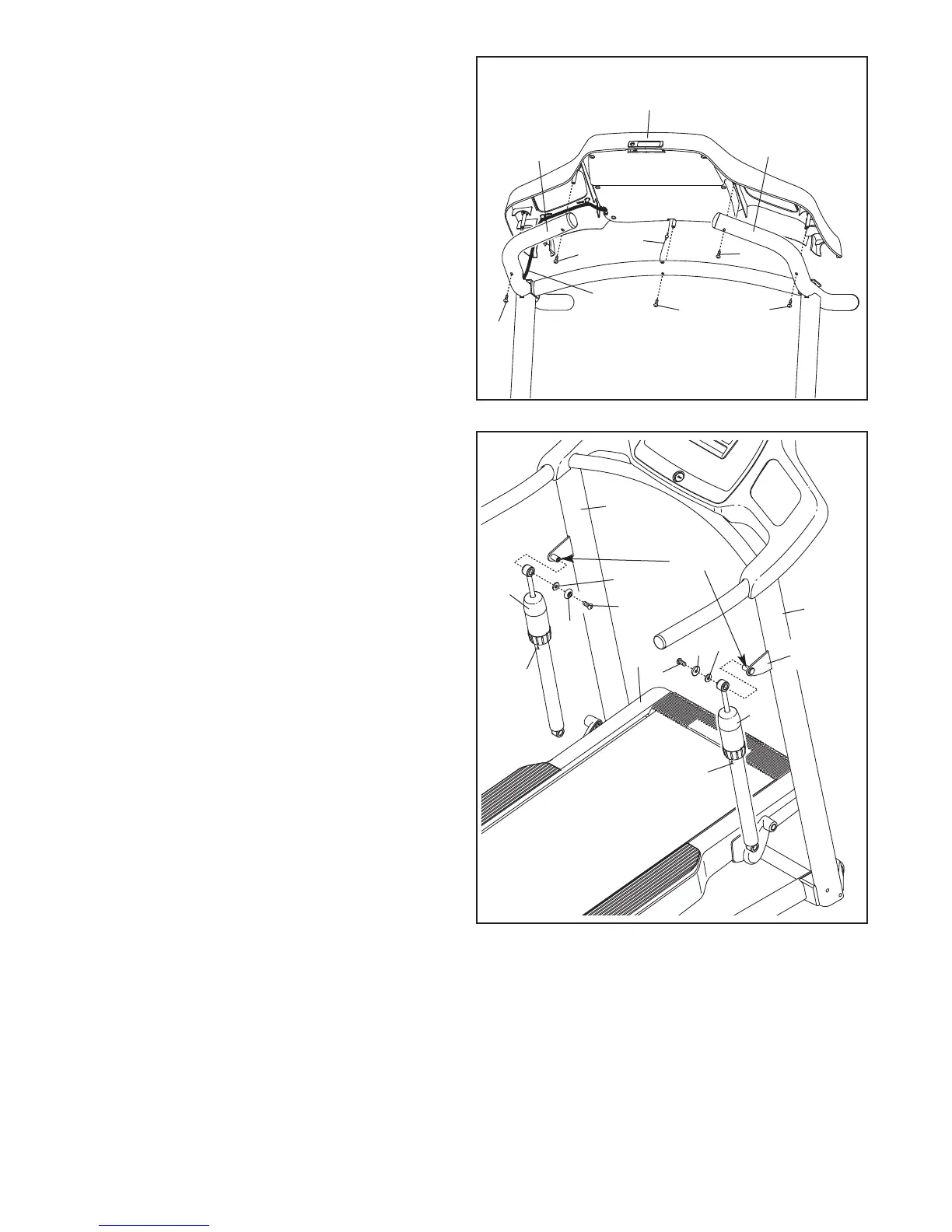
10. Apply a generous amount of the included
grease to the axles on the brackets and to the
Cylinder Spacers (70—see step 11).
Identify an Upper Cylinder Cap (68), which has
a small hole in the center.
Hold a Shock Cylinder (69) near the bracket on
the Right Upright (72). Make sure that the
Shock Cylinder is positioned as shown, with
the arrow facing the rear of the treadmill.
Attach the Shock Cylinder with a 5/16" x 5/8"
Patch Bolt (5), an Upper Cylinder Cap (68), and
an M8 Washer (10) as shown. Do not over-
tighten the Patch Bolt.
Attach the other Shock Cylinder (69) in the
same way.
5
5
68
69
69
64
72
68
10
10
45
9. Set the console assembly on the Left and Right
Handrails (87, 88). Be careful not to pinch any
wires. Insert the excess Upright Wire (91) into
t
he Right Handrail, and insert the Console
Ground Wire (80) into the console assembly.
Attach the console assembly to the Handrails
(87, 88) with five #8 x 3/4" Screws (6). Start all
five Screws before tightening any of them.
See steps 4 and 6. Tighten the 3/8" Jam Nuts
(8).
80
6
6
6
91
88
8
7
6
6
9
Console
Assembly
Bracket
Grease
10
Arrow
Arrow