10
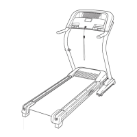
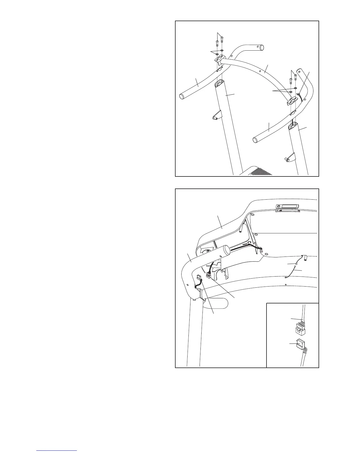
8. With the help of a second person, hold the con-
sole assembly near the Right and Left Handrails
(88, not shown).
Connect the Upright Wire (91) to the console
wire. See the inset drawing. The connectors
should slide together easily and snap into
place. If they do not, turn one connector and try
again. IF THE CONNECTORS ARE NOT CON-
NECTED PROPERLY, THE CONSOLE MAY
BE DAMAGED WHEN YOU TURN ON THE
POWER.
Connect the Console Ground Wire (80) to the
ground wire on the console assembly.
80
91
88
Ground
Wire
8
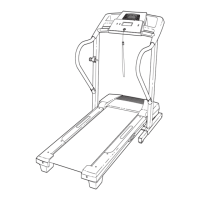
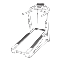
7. Hold the Right Handrail (88) near the Right
Upright (72). Insert the Upright Wire (91)
through the large hole on the bottom of the
Right Handrail. Pull the Upright Wire out of the
h
ole in the side of the Right Handrail.
Set the Right and Left Handrails (88, 87) on the
Right and Left Uprights (72, 64). Attach the
C
rossbar (86) to the Handrails and the Uprights
with four 3/8" x 2 1/4" Patch Bolts (2) and four
3/8" Star Washers (9). Start all four Patch
Bolts before tightening any of them. Be care-
ful not to pinch the Upright Wire (91).
9
2
64
88
72
91
9
86
7
2
91
Console
Wire
Console
Wire
Console
Assembly
8
7