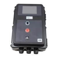
Mechanical and electrical data
Housing dimensions: 215 x 275 x 190 mm
Installation: Fix vertically to the wall
at a minimum height of 1,100 mm
Power supply via 400V/3~ , 50/60 Hz
L1, L2, L3, N, PE: 230V/3~ , 50/60 Hz
L1, N, PE: 230V/3~ , 50/60 Hz,
Power input max. 2200 W,
for power supply 400V/3~
Fuse protection: 10 A K type
Internal consumption of
the control:
max. 250 mA
Control voltage: 24 V
DC, max. 250 mA; protected by self-
resetting fuse for external sensor systems
Control inputs: 24 V
DC, all inputs must be connected so that
they are potential-free. Minimum signal durati-
on for input control command > 100 ms
Control outputs: 24 V DC, max. 250 mA
RS485 A and B: Only for electronic limit switches
RS485level,terminatedwith120Ω
Safety circuit /
Emergency stop:
All input connections MUST be potential-free;
if the safety circuit is interrupted, no further
electrically powered movement of the operator
is possible, not even in deadman mode.
Closing edge safety
device input (performance
level C):
Performance level C
for electrical closing edge safety devices with
8.2kΩterminatingresistorandfordynamic
optical systems.
Photocell
(performance level D):
If the photocell is used as a D performance level
protection system, it must be checked at regular
intervals – at least every 6 months – to ensure
that the system is working properly.
Relay outputs: If inductive loads are connected (e.g. further
relays or brakes), these must be equipped
with suitable interference suppression (such
as recovery diode, varistors or RC circuits).
Potential-free normally open contact; min.
10mA;max.230VAC / 4A.
Once contacts have been used for power
circuits, they can no longer be used for extra-
low current circuits.
Temperature range: Operation: -10°C … +45°C
Storage: -25°C … +70°C
Air humidity: Up to 80% with no condensation
Vibrations: Low-vibration mounting, e.g. on a masonry wall
Type of protection: IP 65
Weight: approx. 1.8 kg
11. Technical data