6 – CS 300 Gate Controls / Rev.D 5.6
5. Initial operation
5.1 General
To guarantee that the equipment functions properly, it must
be ensured that:
− The door is installed and operational.
− The operator motor is installed and ready for operation.
− The command and safety devices are installed and ready
for operation.
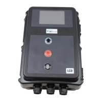
− The control housing with the CS 300 control is installed.
The relevant manufacturers’ instructions must be adhered to
for the installation of the door, the motor, and the command
and safety devices.
5.2 Mains connection
Preconditions
To guarantee that the control unit functions properly, the
following points must be ensured:
− The mains voltage must correspond to the voltage stated
on the type plate.
− The mains voltage must be the same as the voltage of the
operator.
− Forthree-phasecurrent,aclockwiserotatingeldis
required.
− For a permanent connection, an all-pole main switch must
be used.
− For a three-phase connection, only 3-way automatic circuit
breakers (10 A) may be used.
Malfunctions can occur as a result of incorrect
installation of the control!
Beforeswitchingonthecontrolforthersttime,acheck
must be carried out after completing the wiring to ensure
that all the motor connections at the motor and at the
controlissecurelyxed.Allcontrolvoltageinputsare
galvanically isolated from the supply.
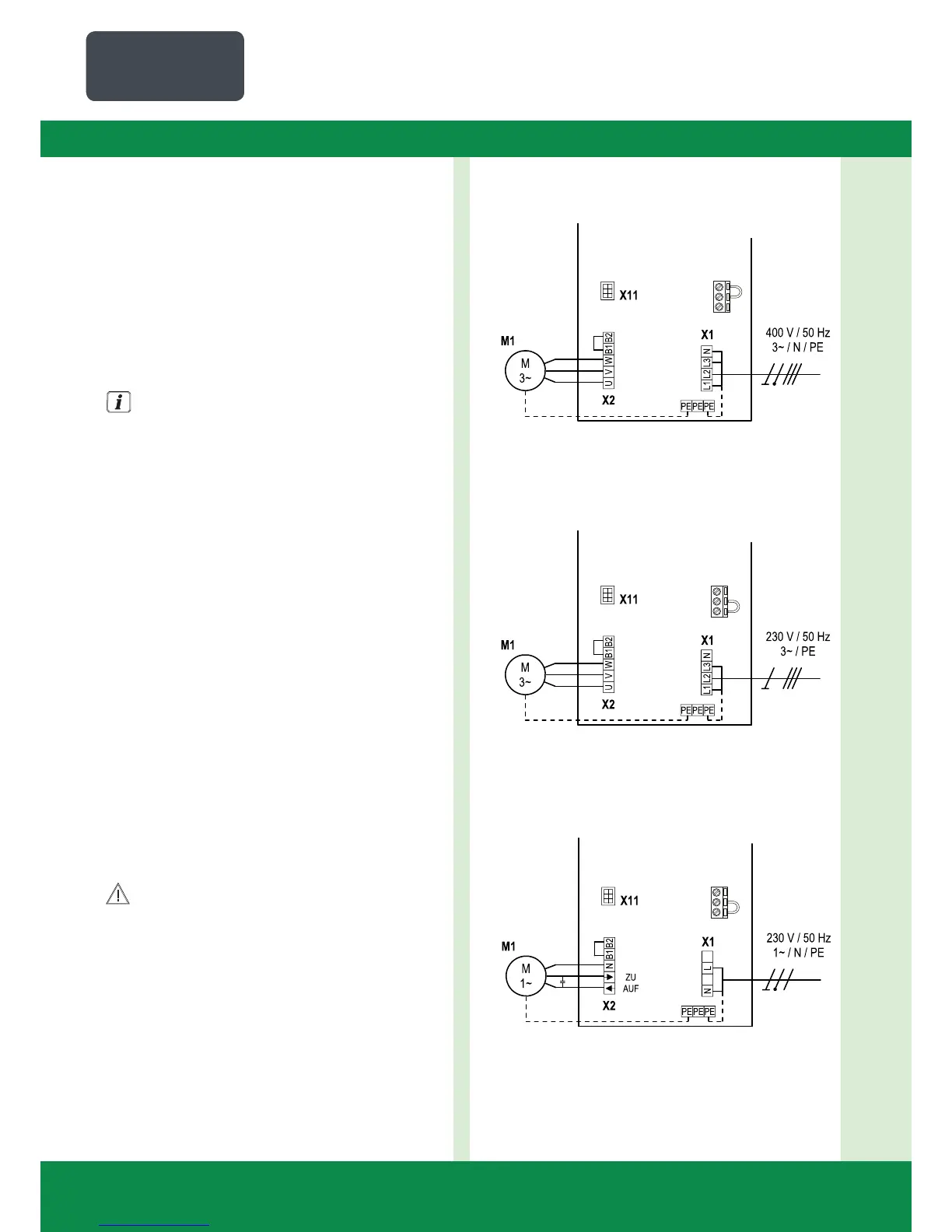
Detailed circuit diagram for mains connection and
motor connection (400 V / three phase)
X14
Detailed circuit diagram for mains connection and
motor connection (230 V / three phase)
X14
Detailed circuit diagram for mains connection and
motor connection (230 V / single phase)
X14