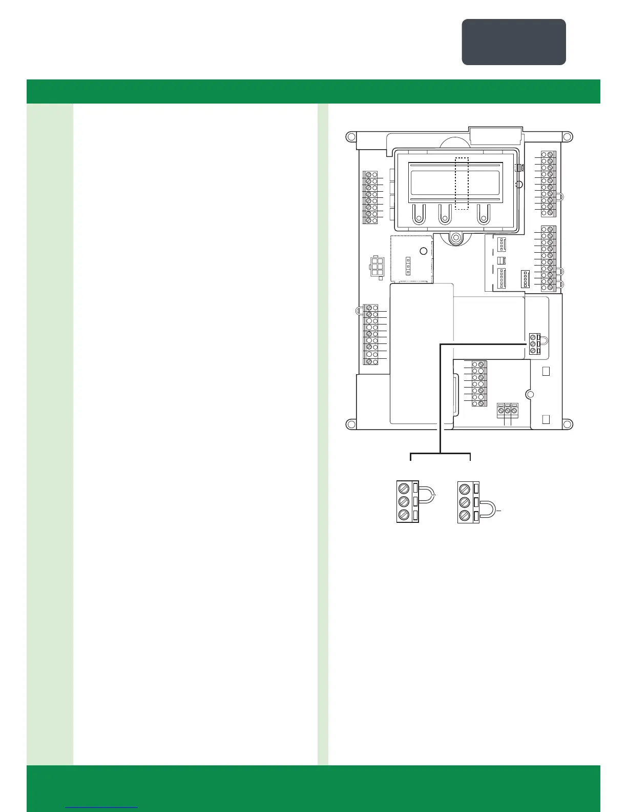
4.2 Motherboard CS 300
(with plugged-in LCD monitor)
Key:
X1: Terminal block for mains connection
X2: Terminal block for motor
X3: Terminal block for command devices
X4: Terminal block for safety elements
X5: Terminal block for relay
X6: Sockets for internal ON-OFF switch
X7: Sockets for internal 3-button input unit
X8: Sockets for LCD monitor
(under the LCD monitor)
X9: Sockets for radio receiver
X10: Sockets for weekly timer
X11: Sockets for digital end position system
X12: Sockets for external radio receiver
X13: Sockets for CS three-button input unit
H4: Closing edge safety device status indicator (green)
ON if closing edge safety device operational
H6: Safety circuit status indicator (amber)
ON if safety circuit closed
S1: Programming button (+)
(on the LCD monitor)
S2: Programming button (–)
(on the LCD monitor)
S3: Programming button (P)
(on the LCD monitor)
1
2
3
4
5
6
7
8
B1
B2
W
V
1
2
3
4
5
6
7
8
9
10
N
L3
L2
L1
X5
X4
X3
X2
X11
X7
X6
X12
PE
PE
PE
X1
X10
1
2
3
4
5
6
7
8
9
10
X8
X9
H4
X13
H6
U
X14
X14
X14