33
tip hole corresponds to the wire diameter that is going to be used. To obtain a high duty cycle without
wire feeding problems it is advisable to install the gas diffuser, the contact tip with 8mm thread and
the nozzle.
For easy welding of Aluminium and good quality welding results it is advisable to work in Pulsed Mode.
(Default Mode with torch 1).
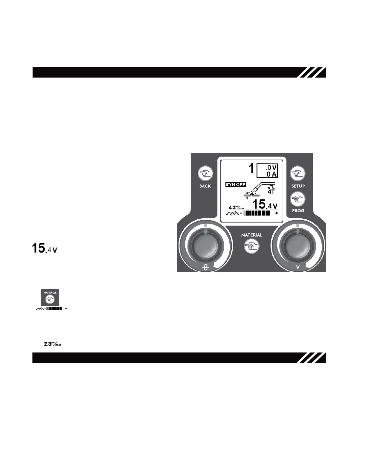
MIG/MAG - SYN OFF WELDING
3.2
5
6.2.1
7.3
2
1
Torch Selection
Press the trigger of the torch that you need to use for welding. The display will view the number correspon-
dent to the selected torch. All parameters that will be changed in the next steps will refer to the selected
torch only.
NOTE: in “SYN OFF” mode torch 1 is automatically associated to the Argon inlet, torch 2 is associated
to the mixed gas inlet.
MIG/MAG Function Setup Key - 3 -
Right Regulation Knob - 5 -
Use the Right Regulation Knob to adjust
the welding voltage.
Material Key - 6.1 -
Use the Material Key to adjust the electronic inductance value.
This setting allows to stabilize the arc by adapting it to the type of material and to the ope-
rator’s hand.
Low Inductance = Cold Arc, more spatters, reactive arc
Induttanza Alta = hot Arc, few spatters, unreactive arc
Left Regulation Knob - 7 -
Use the Left Regulation Knob to adjust the wire speed from 0.8 to 21 m/min (meter per
minute)
Press the Setup Key - 3 - in MIG/MAG Mode to
access the parameters’ setup screen.
Use the Right Regulation Knob
- 5 -
to select the
“Synergy OFF” Mode.
Use the Mode Key - 1 - to go back to the MIG/
MAG main screen.
Figure 25
• Connect the earth cable to the negative output terminal on the front
of the unit.
MIG/MAG - SYN ON/PULSED WELDING
With the torch connected, the wire installed and the gas connection made, earth cable to the Negative
output terminal on the front of the unit.
Torch Selection
Press the trigger of the torch that you need to use for welding. The display will view the number correspon-
dent to the selected torch. All parameters that will be changed in the next steps will refer to the selected
torch only.
NOTE: in “SYN ON” mode torch 1 is automatically associated to the Argon inlet, torch 2 is associated to
the mixed gas or to the Argon inlet depending on the selected synergic curve. Provide gas bottles for both
inlets.
14