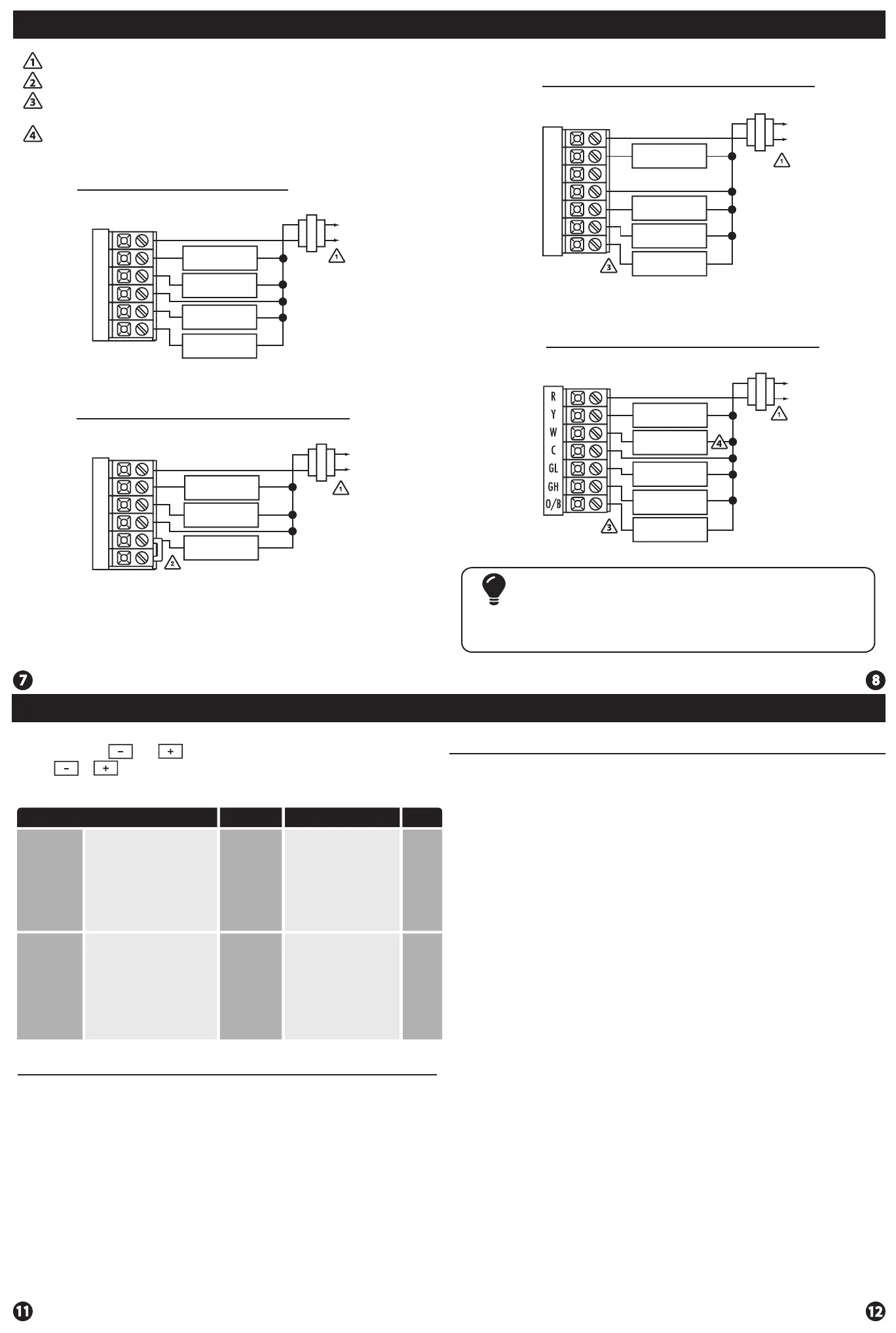
Wiring Diagrams
Power supply
Jumper (not supplied) to connect GL and GH terminals.
Typical 1H/1C System: 2 Speed Fan
Wiring Diagrams
Thermostat must be set to O and B to match the changeover valve, O is the
cool changeover valve, B is the heat changeover valve.
The Aux Heat Relay is energized as the second stage of heat.
R
Y
W
C
GL
GH
COMPRESSOR
RELAY
HEAT RELAY
FAN LOW RELAY
FAN HIGH RELAY
C
R
L1
L2
Typical 1H/1C System: 1 Speed Fan
R
Y
W
C
GL
GH
HEAT RELAY
FAN RELAY
COMPRESSOR
RELAY
Typical 1H/1C Heat Pump System: 2 Speed Fan
R
Y
W
C
GL
GH
O/B
COMPRESSOR
RELAY
CHANGE OVER
VALVE
FAN LOW RELAY
FAN HIGH RELAY
C
R
L1
L2
C
R
L2
L1
Typical 2H/1C Heat Pump System: 2 Speed Fan
C
R
L2
L1
COMPRESSOR
RELAY
AUX HEAT
RELAY
FAN LOW RELAY
FAN HIGH RELAY
CHANGE OVER
VALVE
Most PTAC systems support two speed fan operation. In a single speed
fan PTAC system or conventional single speed fan system, a jumper
should be installed between GL and GH on the thermostat.
Note:
The swing setting, often called
“cycle rate”, “dierential or
“anticipation” is adjustable. A
smaller swing setting will cause
more frequent cucles and a larger
swing setting will cause fewer
cycles.
The heating swing setting is
adjustable from 0.2˚ to 2˚. For
example: A swing setting of
0.5˚ will turn the heating on at
approimately 0.5˚ below the
setpoint and turn the heating
o at approximately 0.5˚ above
the setpoint.
Heating
Swing
(SYSTEM
HEAT)
Swing Settings
Adjustment Options
Default
LCD Will Show
Cooling
Swing
(SYSTEM
COOL)
The swing setting, often called
“cycle rate”, “dierential” or
“anticipation” is adjustable. A
smaller swing setting will cause
more frequent cycles and a larger
swing setting will cause fewer
cycles.
0.8˚
The cooling swing setting is
adjustable from 0.2˚ to 2˚. For
example: A swing setting of
0.5˚ will turn the cooling on at
approximately 0.5˚ above the
setpoint and turn the cooling
o at approximately 0.5˚
below the setpoint.
08
08
Swing Setting
The second stage of Heat will turn on at 2x the swing setting. The second
stage will turn o when 1x the swing is reached. For example, if the swing
setting is 0.8˚ for heating and the thermostat is set at 70˚ F, the rst stage will
turn on at approximately 69.2˚ F. The second stage will turn on at 68.4˚F and the
rst will turn o at 70.8˚ F.
0.8˚
1. Set the thermostat system switch to the desired position (COOL or HEAT).
2. Press and hold and together for 3 seconds.
3. Use or to adjust desired swing setting. (The display reads in tenths of a degree.)
4. To exit, move system switch or wait 15 seconds.
Swing Setting
Specications
Specications
The display range of temperature ... 41˚F to 95˚F (5˚C to 35˚C)
The control range of temperature.... 44˚F to 90˚F (7˚C to 32˚C)
Load rating.................................................1 amp per terminal, 1.5 amp
maximum all terminals combined
Swing (cycle rate or dierential) ...... Heating is adjustable from 0.2˚ to 2.0˚
Cooling is adjustable from 0.2˚ to 2.0˚
Power source ...........................................18 to 30 VAC, NEC Class II, 50/60 Hz
for hardwire
Battery power from 2 AA Alkaline
batteries
Operating ambient ............................... 32˚F to +105˚F (0˚C to +41˚C)
Operating humidity .............................. 90% non-condensing maximum
Dimensions of thermostat ................. 4.7”W x 4.4”H x 1.1”D
Frequency ................................................ 916 MHz
T631-2 Thermostat
 Loading...