Do you have a question about the Pro1 Technologies T731W and is the answer not in the manual?
Optimal placement for average temperature and good air circulation.
Instructions for mounting the subbase horizontally or vertically.
Crucial safety warning about disconnecting power before installation.
Information regarding mercury-free products and proper disposal.
Guide on installing AA batteries, noting it's optional if hardwired.
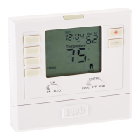
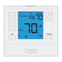
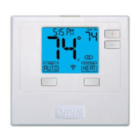
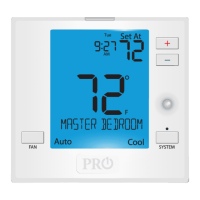
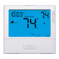
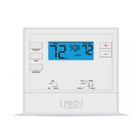
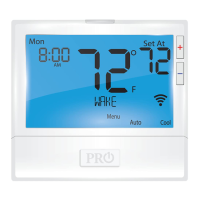
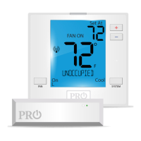
Explanation of current room temperature, low battery, and system operation indicators.
Description of setpoint display and active heat/cool stages.
Details on low battery indicator behavior and consequences of not replacing batteries.
Crucial safety warning about disconnecting power before installation.
Table mapping wire terminals to system functions for Heat Pump and Conventional.
Guidance on terminal block screws, wire specifications, and C terminal usage.
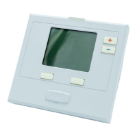
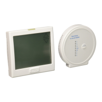
Instructions for connecting the base module to a PTAC unit.
Recommendations for mounting the base module inside or outside PTAC units.
Procedure to access the technician setup menu using thermostat buttons.
Key information regarding transferring tech settings to the base module.
Adjusting the thermostat's displayed temperature reading.
Configuring cycle rate (differential) for cooling and heating.
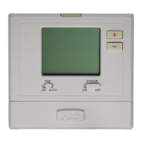
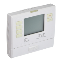
Selecting fan control (Electric/Gas) and number of fan speeds.
Designating the terminal for medium speed fan operation.
Choosing between Fahrenheit (°F) or Celsius (°C) for temperature display.
Configuring the display backlight to stay on or activate on key press.
Selecting Heat Pump (default) or Conventional system type.
Enabling or disabling the 5-minute delay for compressor restart.
Setting maximum/minimum temperature limits for heating and cooling.
Steps to pair the thermostat with the base module for wireless communication.
Steps to unpair the thermostat from the base module network.
Selecting the changeover valve setting (O or B) for heat pump applications.
Enabling/disabling the occupancy sensor for temperature setbacks.
Configuring duration, occupied, and unoccupied temperature settings.
Adjusting the sensitivity level of the occupancy sensor.
Guidelines for pairing thermostats with the base module and ensuring connection.
Information on base module capacity, repeater function, and device updates.
Details on temperature range, load rating, power source, and dimensions.
Details on load rating, power source, operating ambient, and humidity.
| Hold Feature | Yes |
|---|---|
| Filter Change Alert | Yes |
| Backup Memory | Yes |
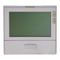
| Display | Large LCD |
| Programmability | 7-Day |
| Type | Digital |
| Compatibility | Conventional systems |
| Warranty | 5 years |