11.0 Customer Wiring Connections
All wiring connections are made to three quick-disconnect connectors mounted on the rear of the sensor
enclosure. These connectors may have different signals coming to them from inside the sensor. The
following diagrams show the standard configurations for these connectors.
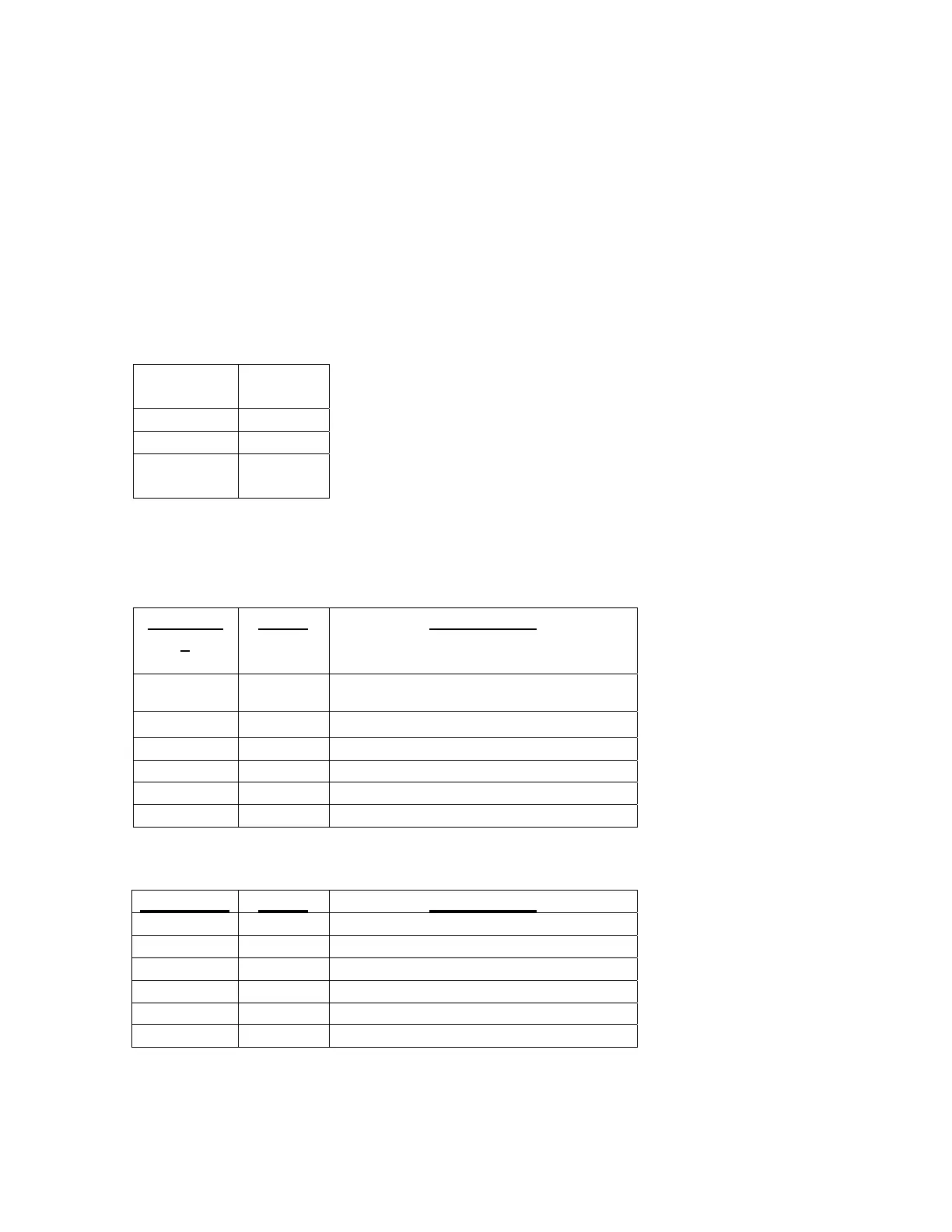
POWER
Terminal
#
Input
1 Live
2 Neutral
Gnd
Symbol
Ground
ANALOG Connector (4-20mA outputs) – Standard configuration
Terminal
#
Signal
Constituent #
1
Gnd
1
2 4-20 mA
1
3 Gnd 2 (1 if sensor is in single mode)
4 4-20 mA 2 (1 if sensor is in single mode)
5 Gnd 3 (not operational in single mode)
6 4-20 mA 3 (not operational in single mode)
ANALOG Connector (0-10V outputs) – Alternate 1
Terminal # Signal Constituent #
1 Gnd 1
2 0-10V 1
3 Gnd 2 (1 if sensor is in single mode)
4 0-10 V 2 (1 if sensor is in single mode)
5 Gnd 3 (not operational in single mode)
6 0-10 V 3 (not operational in single mode)
36