Do you have a question about the Process Sensors MCT 300 and is the answer not in the manual?
Describes the quartz-halogen light bulb that generates infrared energy.
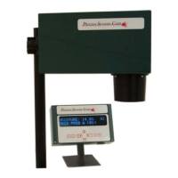
Proper positioning and orientation of the sensor for optimal performance.
Information on powering the sensor via AC input and recommended practices.
Explains rear I/O connector usage for data transmission.
Details the display unit with keypad for setup and routine interaction.
Procedure for adjusting the zero offset for accurate calibration.
Procedure for adjusting the span for accurate calibration.
Standard configuration for 4-20mA analog output terminals.
Alternate configuration for 0-10V analog output terminals.
Procedure for cleaning the sensor window to ensure accurate readings.
Procedure for adjusting the IRt/c sensor's zero/offset for accuracy.
| Accuracy | ±0.1% |
|---|---|
| Enclosure Rating | IP65 |
| Output | 4-20 mA |
| Emissivity | 0.10 to 1.00 adjustable |
| Spectral Response | 8 to 14 µm |
| Operating Temperature | 0 to 60°C (32 to 140°F) |