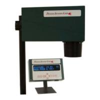
MCT Enclosure
The MCT sensor has two-part cast aluminum housing. The two sections are held together by four
machine screws. These screws are held captive in the bottom half of the housing. Unscrew the four
screws and place the upper half to one side.
Lamp Replacement
This operation requires that the optical bench be removed from the bottom half of the sensor
enclosure.
1. Unplug the analog cable from the main PCB.
2. Unplug the digital cable from the main PCB.
3. Locate the 6 screws that hold the optical bench into the enclosure.
4. Remove these screws and gently lift out the optical bench. The optical bench will still be
connected to the power supply by the AC input cable. Remove this cable from the power supply.
5. Remove the two Allen screws that hold the power supply to the main board.
6. Disconnect the DC cable harness from the main board.
7. Unplug the lamp from the power supply.
8. Lay the sensor on its side and locate the two Allen screws that hold the lamp into the optical
bench.
9. Remove both screws and take out the damaged lamp.
10. Install a new lamp assembly; do not touch the lamp glass with bare fingers.
11. Re-fit the retaining screws.
12. Re-connect the lamp to the power supply.
13. Re-connect the power supply harness and the power supply assembly to the main board.
14. Re-connect the AC cable to the power supply.
15. Re-install the optical bench in the bottom half of the enclosure.
16. Re-connect the Analog and digital cable to their respective sockets on the main board.
Motor Replacement
This operation requires that the optical bench be removed from the bottom half of the sensor
enclosure.
1. Unplug the analog cable from the main PCB.
2. Unplug the digital cable from the main PCB.
3. Locate the 6 screws that hold the optical bench into the enclosure.
4. Remove these screws and gently lift out the optical bench. The optical bench will still be
connected to the power supply by the AC input cable. Remove this cable from the power supply.
5. Remove the two Allen screws that hold the power supply to the main board.
6. Disconnect the DC cable harness from the main board.
7. Remove the four Allen crews that hold the dome mirror/detector plate assembly to the optical
bench. Disconnect the detector from the main board and set the assembly aside.
8. Remove the two Allen screws that hold the motor in the optical bench. Unplug the old motor
from the main board.
42