15
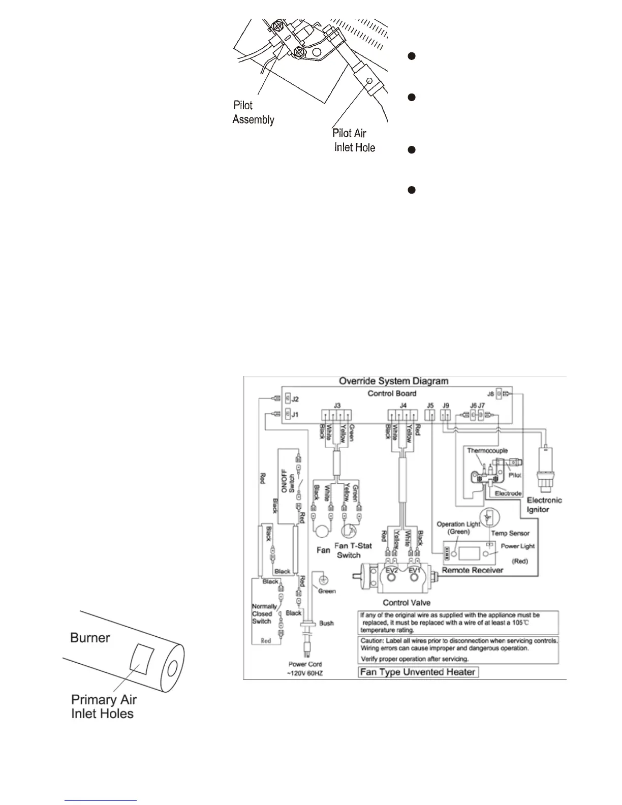
Figure 24 - Pilot Air Inlet Hole
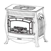
Figure 23 - Burner Primary Air
Inlet
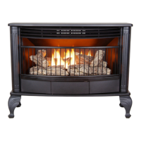
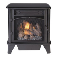
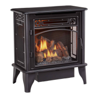
MAIN BURNER
Periodically inspect all burner flame
holes with the heater running. All slotted
burner flame holes should be open with
yellow flame present. All round burner
flame holes should be open with a small
blue flame present. Some burner flame
holes may become blocked by debris or
rust, with no flame present. If so, turn off
heater and let cool. Either remove block -
age or replace burner. Blocked burner
flame holes will create soot.
We recommend you keep the burner
and pilot assembly clean and free of
dust and dirt.
To clean these parts we recommend
using compressed air no greater than
30 PSI. Your local computer store, hard -
ware store, or home center may carry
compressed air in a can. You can use a
vacuum cleaner in the blow position. If
using compressed air in a can, please
follow the directions on the can. If you
don’t follow directions on the can, you
could damage the pilot assembly.
1. Shut off the unit, including the
pilot. Allow the unit to cool for
at least thirty minutes.
2 . I n s p e c t b u r n e r , p i l o t a n d
p r i m a r y a i r i n l e t h o l e s on
injector holder for dust and dirt
(See Figure 23).
3 . B l o w a i r t h r o u g h t h e
po r t s / slots an d holes i n the
burner.
4. C h e c k t h e i n j e c t o r h o l d e r
l o c a t e d a t t h e en d o f th e
bur n er tub e a gai n . R em o ve
any large particles of dust, dirt,
lint, or pet hair with a soft cloth
or vacuum cleaner nozzle.
5. Blow air into the primary air
holes on the injector holder.
6. In case any large clumps of
dust have now been pushed
into the burner repeat steps 3
and 4.
Clean the pilot assembly also. A yel -
low tip on the pilot flame indicates dust
and dirt in the pilot assembly. There is
a small air inlet hole about two inches
from where the pilot flame comes out of
the pilot assembly (see Figure 24). With
the unit off, lightly blow air through the
air inlet hole. You may
blow through a drinking straw if com -
pressed air is not available.
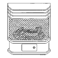
Figure 25 - Override Control System Diagram
CABINET
Air Passageways
Use a vacuum cleaner or pressurized
air to clean.
Exterior
Use a soft cloth dampened with a mild
soap and water mixture. Wipe the
cabinet to remove dust.
Logs
If you remove logs for cleaning, refer
to Installing Logs to properly replace
logs.
Replace logs if broken or chipped
(dime size or larger).