PANNELLO POSTERIORE Italiano
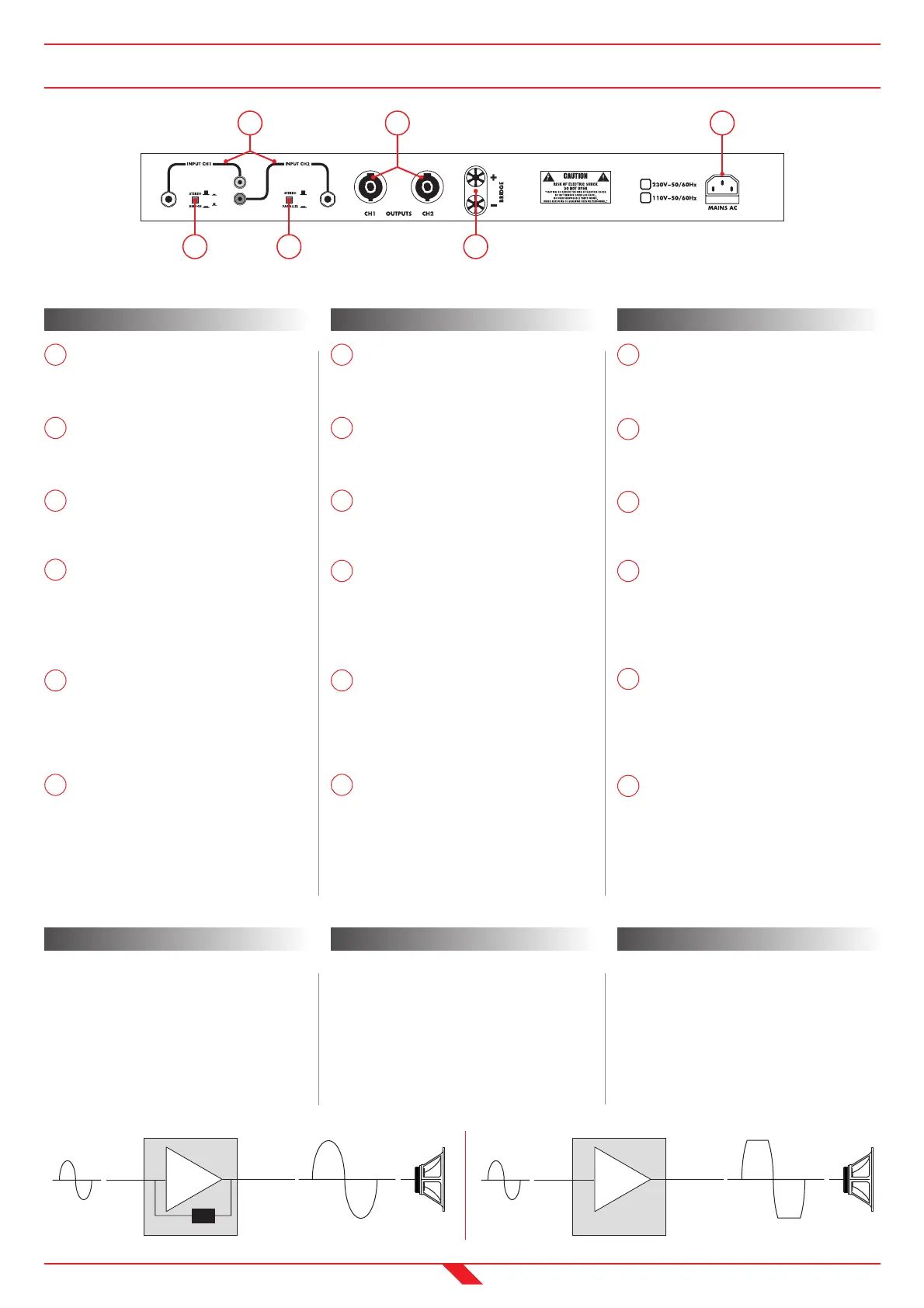
INGRESSI
Ingressi bilanciati con Jack stereo da
1
/
4
” e sbilanciati su pin-RCA.
PULSANTE “STEREO/BRIDGE”
Selettore per le modalità “Stereo” e
“Bridge”.
PULSANTE “STEREO/PARALLEL”
Selettore per le modalità “Stereo” e
“Parallel”.
USCITE DI POTENZA CH1 E CH2
Uscite di potenza su 2 connettori a 4 poli
SPK4MP collegati su 1+/1-. L’impedenza
nominale dei sistemi acustici utilizzati
non deve essere inferiore a 4Ω.
USCITA DI POTENZA “BRIDGE”
Uscita di potenza “Bridge” sui morsetti a
serrare (rosso+/nero-). L’impedenza nomi-
nale del sistema acustico utilizzato non
deve essere inferiore a 8Ω.
PRESA DI ALIMENTAZIONE
Presa a vaschetta con fusibile di protezio-
ne. In caso di rottura sostituire con fusi-
bile ritardato da 5x20mm, T2A (230V) o
T4A (115V).
REAR PANEL English
INPUTS
1
/
4
” Jack stereo balanced inputs and
RCA-pins unbalanced inputs.
“STEREO/BRIDGE” SELECTOR
Switch selector for “Stereo” and “Bridge”
mode.
“STEREO/PARALLEL” SELECTOR
Switch selector for “Stereo” and “Parallel”
mode.
CH1 AND CH2 POWER OUTPUTS
Power outputs on two 4-poles SPK4MP
connectors, connected on 1+/1-. The
nominal impedance of loudspeaker enclo-
sure must not be less than 4Ω.
“BRIDGE” POWER OUTPUT
Power outputs on the binding posts
(red+/black-), connected on 1+/1-. The
nominal impedance of loudspeaker enclo-
sure must not be less than 8Ω.
MAINS SOCKET
AC socket with protection fuse.
If the fuse blows it must be replaced with
delayed fuse 5x20mm, T2A (230V) or T4A
(115V).
PANEL TRASERO Español
ENTRADAS
Entradas balanceadas con Jack estéreo de
1/4” y no balanceadas en pin-RCA.
PULSADOR “STEREO/BRIDGE”
Selector para los modos “Stereo” y
“Bridge”.
PULSADOR “STEREO/PARALLEL”
Selector para los modos “Stereo” y
“Parallel”.
SALIDAS DE POTENCIA CH1 Y CH2
Salidas de potencia en dos conectores de
cuatro polos SPK4MP, conectados en 1+/1.
La impedancia nominal de los sistemas acú-
sticos utilizados no debe ser inferior a 4Ω.
SALIDA DE POTENCIA “BRIDGE”
Salida de potencia “Bridge” en los bornes
para apretar (rojo+/negro-). La impedan-
cia nominal del sistema acústico utilizado
no debe ser inferior a 8Ω.
TOMA DE ALIMENTACION
Toma AC con fusible de protección.
En caso de rotura sustituir con fusible
retrasado de 5x20mm, T2A (230V) o T4A
(115V).
5
6
7
8
9
10
6
7
8
9
10
6
7
8
9
10
5 5
OSC™ Italiano
• CIRCUITO DI CONTROLLO
DELLA SATURAZIONE
Il circuito OSC™ controlla in tempo reale che
il segnale non saturi mai, sia in presenza di
un eccessivo segnale in ingresso, sia in pre-
senza di una tensione di alimentazione
variabile rispetto al valore nominale di 230V
AC o 115V AC fino al 25% in meno.
OSC™ Español
• CIRCUITO DE CONTROL DE RECORTE
El circuito OSC™ controla en tiempo real
que la señal no sature nunca, tanto en
presencia de una excesiva señal en entra-
da, tanto en presencia de un voltaje de
alimentación variable en relación con el
valor nominal de 230V AC o 115V AC hasta
el 25% menos.
OSC™ English
• OUTPUT SENSE CLIPPING
The OSC™ controls in real time that the
signal never clips, either when the input
signal is too high or when the mains power
is variable compared to the 230V AC or 115V
AC nominal values till 25% less.