Rev.20170601 V1.0E HPC INSTALLATION & OPERATION MANUAL 10
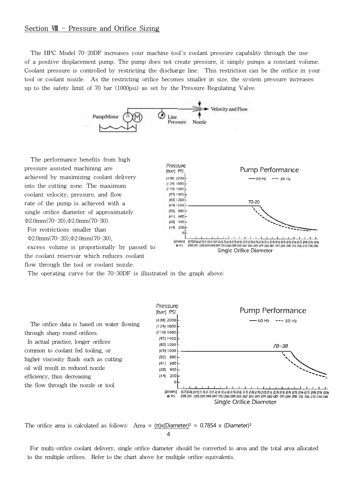
Section Ⅷ - Pressure and Orifice Sizing
The HPC Model 70-20DF increases your machine tool's coolant pressure capability through the use
of a positive displacement pump. The pump does not create pressure, it simply pumps a constant volume.
Coolant pressure is controlled by restricting the discharge line. This restriction can be the orifice in your
tool or coolant nozzle. As the restricting orifice becomes smaller in size, the system pressure increases
up to the safety limit of 70 bar (1000psi) as set by the Pressure Regulating Valve.
The performance benefits from high
pressure assisted machining are
achieved by maximizing coolant delivery
into the cutting zone. The maximum
coolant velocity, pressure, and flow
rate of the pump is achieved with a
single orifice diameter of approximately
Φ
2.0mm(70-20),
Φ
2.0mm(70-30).
For restrictions smaller than
Φ
2.0mm(70-20),
Φ
2.0mm(70-30),
excess volume is proportionally by passed to
the coolant reservoir which reduces coolant
flow through the tool or coolant nozzle.
The operating curve for the 70-30DF is illustrated in the graph above:
The orifice data is based on water flowing
through sharp round orifices.
In actual practice, longer orifices
common to coolant fed tooling, or
higher viscosity fluids such as cutting
oil will result in reduced nozzle
efficiency, thus decreasing
the flow through the nozzle or tool.
The orifice area is calculated as follows: Area
= (π)x(Diameter)² = 0.7854 x (Diameter)²
4
For multi-orifice coolant delivery, single orifice diameter should be converted to area and the total area allocated
to the multiple orifices. Refer to the chart above for multiple orifice equivalents.