EasyManua.ls Logo

profluid PF70-30DFS - User Manual

profluid PF70-30DFS
14 pages
Print Icon
To Next Page IconTo Next Page
Loading...
High Pressure Coolant System Packages
INSTALLATION & OPERATION MANUAL
HPC Model PF70-30DFS (SFS)
Rev.20170601 V1.0E
*CONTENTS OF THIS MANUAL ARE SUBJECT TO CHANGE WITHOUT NOTICE.
1156, Dudong-ro, Dudong-myeon, Ulju-gun, Ulsan, Korea.
TEL : 82-52-289-4035 FAX : 82-52-289-4037 www.kemtech.co.kr
Question and Answer IconNeed help?

Do you have a question about the profluid PF70-30DFS and is the answer not in the manual?

Summary

Safety Precautions and System Considerations

SAFETY PRECAUTIONS

Read and follow all instructions and safety warnings before operating this high pressure system.

SYSTEM PRECAUTIONS

Safety Valve: HPC Systems generate pressure by positive displacement. A Bypass Pressure Regulating Valve is provided.

Considerations before Installation

Verify that your entire coolant delivery system is capable of supporting your desired operating pressure.

Installation Guidelines

LOCATING THE PUMPING SYSTEM

The HPC Unit should be located to minimize the required hose lengths between the HPC and your machine.

INLET PLUMBING

Do not use inlet hoses or components smaller than 15.9mm (5/8") I.D. Use thread sealant on any PT/NPT fittings.

Electrical Installation

POWER CONNECTION

The HPC 70-00DF(SF) is shipped from the factory wired for Low Voltage operation (60HZ 220V).

Alarm Control Circuit

The HPC is equipped with a Pressure Switch and a Differential Pressure Switch to monitor coolant supply conditions.

Pressure Sensing Connection

The 70-00DF(SF) Pressure Switch is plumbed to the HPC inlet fitting to monitor coolant supply.

Differential Pressure Sensing Connection

The 70-00DF(SF) Differential Pressure Switch is plumbed to the filter inlet and outlet fittings to monitor differential pressure.

Prior to Initial Start-Up

PROCEDURE FOR PURGING AIR FROM FILTER CANISTER

Follow these steps to purge air from the filter canister: Close drain valves, command system OFF, then coolant ON.

System Startup

START-UP PROCEDURE

Verify coolant level, turn on power, ensure system is primed, check inlet pressure, and listen for noise.

Setting Pressure; Pressure Regulating Valve

To Check the Regulator Set Point

Turn Adjusting Nut counterclockwise to decrease spring tension, then clockwise to set desired pressure.

Pressure and Orifice Sizing

Filter Replacement Instructions

Preventative Maintenance

DAILY CHECKS

Check the active filter's inlet pressure gauge. A higher inlet coolant supply pressure must be regulated.

PERIODIC CHECKS

Check the oil level and condition, inspect hoses, fittings, and nozzles for wear or damage.

Troubleshooting the 70-00 DFS(SFS) Pump

HPC SYSTEMS WARRANTY

What Is Covered

Warrants that the HPC Systems product will conform to manufacturer's specifications and be free from defects in workmanship and material for one year.

What We Will Do To Correct Problems

Notify distributor, and they will, at their option, repair or replace the defective unit at no charge for parts or labor.

What This Warranty Does Not cover

Does not apply to defects caused by fault, negligence, misuse, improper installation, or disasters.

Overview

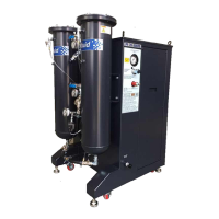
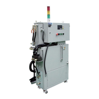
The document describes the HPC Model PF70-30DFS (SFS), a High Pressure Coolant System Package manufactured by Kemtech under the "profluid" brand. This system is designed to provide high-pressure coolant for machine tools, enhancing machining performance by delivering coolant into the cutting zone at elevated pressures and flow rates.

Function Description

The HPC Model PF70-30DFS (SFS) is a positive displacement pump system that increases a machine tool's coolant pressure capability. It does not create pressure directly but rather pumps a constant volume of coolant. The coolant pressure is controlled by restricting the discharge line, which can be an orifice in the tool or coolant nozzle. As the restricting orifice becomes smaller, the system pressure increases up to a safety limit of 70 bar (1000 psi), as set by the Pressure Regulating Valve.

The system includes a dual filter assembly for coolant filtration, ensuring clean coolant delivery to the machine tool. It features an inlet pressure gauge, air purge line, coolant inlet, filter select valve, differential pressure switch, pressure gauge, coolant reservoir return, filter drain valve, and locking level bolts. An alarm control circuit monitors coolant supply conditions at the pump inlet using a Pressure Switch and a Differential Pressure Switch. The Pressure Switch signals a coolant supply problem if inlet pressure drops below 0.2 Bar (2.5 psi), while the Differential Pressure Switch activates when the pressure difference across the filter indicates a need for filter maintenance (typically 8-10 psi/d).

The system is designed to maximize coolant delivery into the cutting zone, achieving optimal coolant velocity, pressure, and flow rate with a single orifice diameter of approximately Φ2.0mm (for 70-20 and 70-30 models). For restrictions smaller than this, excess volume is bypassed to the coolant reservoir, reducing flow through the tool or nozzle.

Important Technical Specifications

  • Model: PF 70-30 DFS (SFS)
  • Main Power: 3Ph 220Vac 50/60Hz
  • Motor: 3Ph 220/380Vac 50/60Hz, 7.5KW 27.6/26.1A
  • Required Inlet Pressure: 1.2~4.1 Bar (17~59 PSI)
  • Maximum Discharge Pressure: 70 Bar (1015 PSI)
  • Volume (50/60Hz): 24 LPM (6.3 GPM) / 30 LPM (7.9 GPM)
  • Discharge Fitting: 1/2" (-12) JIS37
  • INLET Hose Fitting: 1"
  • DRAIN Hose Fitting: 3/4"
  • Orifice: 2.46 mm
  • Dimensions: 835 x 736 x 1339H mm
  • Ship Weight: 295 Kg (Standard)
  • Filter System: Includes two filter assemblies.
  • Filtration: High capacity filter bag elements rated at 100, 50, 25, 10, or 5-micron are available.
  • Coolant Viscosity: Can pump coolants or oils of viscosity down to 125 SUS (CST:26).

Usage Features

  • Pressure Regulation: A Bypass Pressure Regulating Valve acts as a safety valve to control maximum system pressure and prevent over-pressurization. It is crucial not to remove or incorrectly adjust this valve. The valve's adjusting bolt should be backed out counter-clockwise to relieve spring tension before initial startup, ensuring the pump starts under minimum pressure.
  • Inlet Pressure Management: A positive head pressure must be maintained at the HPC inlet to prevent cavitation. The filter vessels have a maximum pressure rating of 4.1 Bars (60psi). If the supply pump provides excessive inlet pressure, it must be regulated to this maximum.
  • Hose Guidelines: Flexible hoses of at least 0.9M (3 ft.) are recommended between the HPC discharge fitting and the machine to reduce vibration. Discharge hose size should be 12.7mm (1/2") I.D. and not smaller than 9.5mm (3/8") I.D. Inlet plumbing should avoid shutoff valves smaller than 19mm (3/4") I.D. and prefer 45° fittings over 90° for elbows.
  • Orifice Sizing: The system's performance is directly related to the orifice size. The manual provides graphs and formulas for calculating orifice area and selecting appropriate sizes for single or multiple orifice coolant delivery to achieve desired pressure and flow.
  • Air Purging: A procedure is outlined for purging air from the filter canisters using the filter drain valves and the air purge/drain hoses, ensuring only coolant is discharged.
  • System Startup: Detailed steps for initial startup include verifying coolant levels, turning on power, checking inlet pressure (1.2-4.1 Bar), listening for erratic noise, and priming the system if air locks are present.
  • Pressure Setting: Instructions are provided for setting the Pressure Regulating Valve using a supplied calibrating orifice. The HPC unit should not be run in production with the calibrating orifice installed, as this will over-restrict flow and bypass coolant to the reservoir.

Maintenance Features

  • Pump Lubrication: Oil in the crankcase should be changed after the first 50-100 hours of operation, and every 500 hours thereafter. Approximately 25 liters (845 oz) of approved oil are required. The pump must never be run without oil in the crankcase.
  • Filtration: Filter replacement is required when the differential pressure across the filter element reaches 0.8 Bar (8-10 psi). The manual provides detailed instructions for replacing filter elements, including opening drain valves, relieving pressure, removing lids, and installing new elements.
  • Daily Checks: Regularly check the active filter's inlet pressure gauge to ensure it is within the 4.1 Bar (60psi) maximum rating.
  • Periodic Checks: Check the oil level and condition in the pump reservoir via the sightglass (1/2 to 2/3 full is acceptable). Inspect high-pressure coolant circuit components, replacing worn or damaged hoses and tightening leaking fittings. Periodically verify the discharge pressure gauge to ensure the HPC is operating at the desired pressure.
  • Troubleshooting: A comprehensive troubleshooting chart is provided, listing common problems (e.g., low pressure, rough pump operation, coolant leakage, coolant in crankcase, premature packing failure) with their probable causes and corresponding solutions. Solutions include replacing filter elements, cleaning valves, adjusting the unloader, checking for airtight seals, repairing seals, replacing oil seals, replacing plungers, and reducing inlet pressure.

The manual emphasizes safety precautions, including wearing safety glasses, ensuring machine guards are in place, never directing coolant streams at persons, and never adjusting the Pressure Regulating Valve to increase pressure without a properly sized discharge orifice. It also provides a warranty statement covering defects in workmanship and material for one year from the manufacturer's shipment date.

profluid PF70-30DFS Specifications

General IconGeneral
Brandprofluid
ModelPF70-30DFS
CategoryIndustrial Equipment
LanguageEnglish

Related product manuals