Rev.20170601 V1.0E HPC INSTALLATION & OPERATION MANUAL 9
Section Ⅵ - System Startup
START-UP PROCEDURE
1. Verify coolant level in machine reservoir is at least 3/4 full.
2. Turn on power to both the supply pump and the HPC pump.
3. A fully primed system will run smoothly and deliver steady flow. Check the inlet pressure.
Inlet pressure 1.2Bar(14psi)~4.1Bar(60psi).
4. Listen for any erratic noise; look for unsteady flow.
5. If the system has an air lock in the high pressure lines, the pump may fail to prime. Follow the instructions
for Setting Pressure below to remove air that may be trapped in the pump manifold and high pressure lines.
Section Ⅶ - Setting Pressure / Pressure Regulating Valve
The Pressure Regulating Valve is the system safety valve to prevent over-pressurization.
Under no
circumstances
should the setting be higher than 70 Bar(1000 psi) for HPC Model 70-00DF(SF).
To Check the Regulator Set Point:
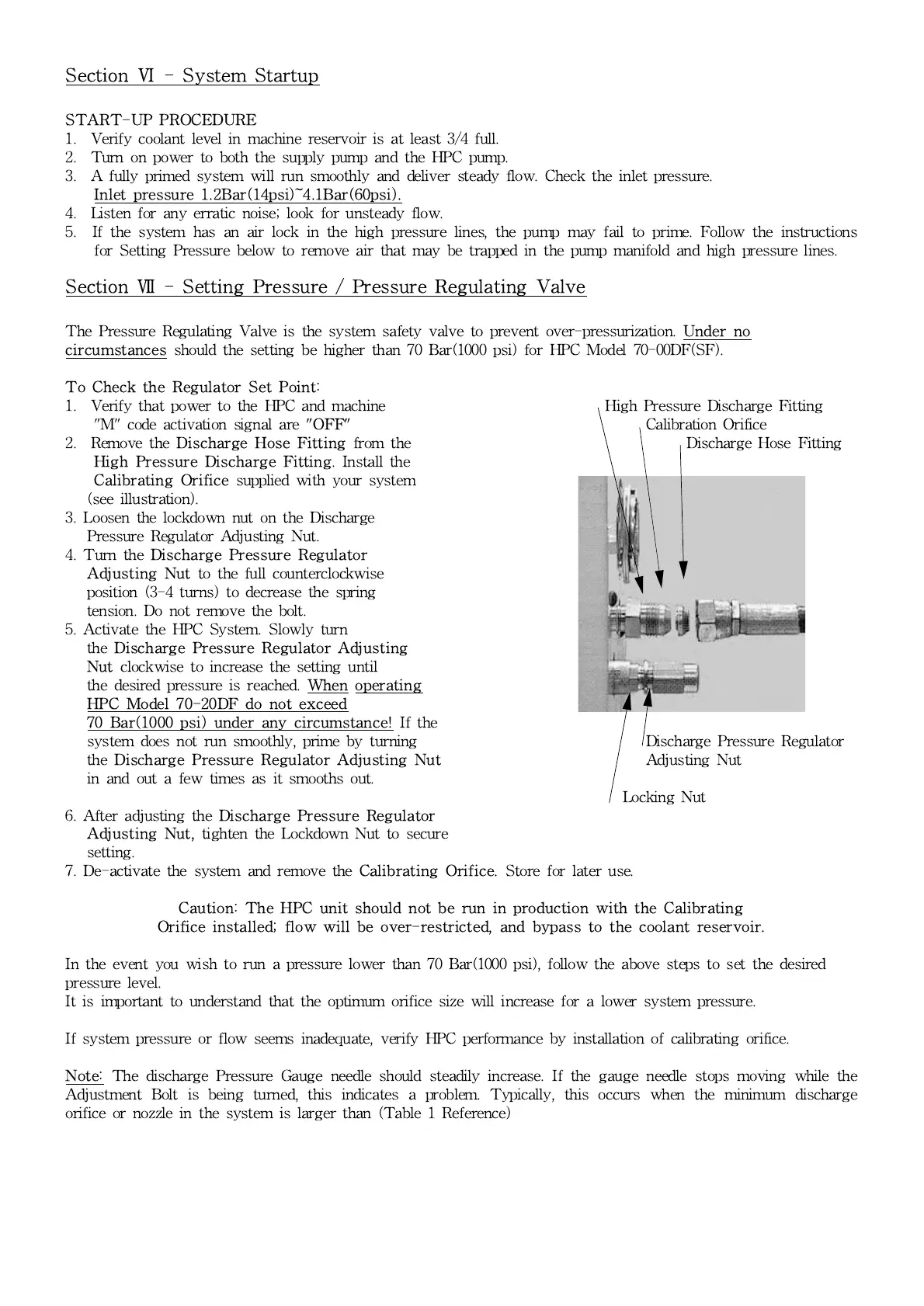
1. Verify that power to the HPC and machine High Pressure Discharge Fitting
"M" code activation signal are
"OFF"
Calibration Orifice
2. Remove the
Discharge Hose Fitting
from the Discharge Hose Fitting
High Pressure Discharge Fitting
. Install the
Calibrating Orifice
supplied with your system
(see illustration).
3. Loosen the lockdown nut on the Discharge
Pressure Regulator Adjusting Nut.
4. Turn the
Discharge Pressure Regulator
Adjusting Nut
to the full counterclockwise
position (3-4 turns) to decrease the spring
tension. Do not remove the bolt.
5. Activate the HPC System. Slowly turn
the
Discharge Pressure Regulator Adjusting
Nut
clockwise to increase the setting until
the desired pressure is reached.
When operating
HPC Model 70-20DF do not exceed
70 Bar(1000 psi) under any circumstance!
If the
system does not run smoothly, prime by turning Discharge Pressure Regulator
the
Dis
c
harge Pressure Regulator Adjusting Nut
Adjusting Nut
in and out a few times as it smooths out.
Locking Nut
6. After adjusting the
Discharge Pressure Regulator
Adjusting Nut,
tighten the Lockdown Nut to secure
setting.
7. De-activate the system and remove the
Calibrating Orifice.
Store for later use.
Caution: The HPC unit should not be run in production with the Calibrating
Orifice installed; flow will be over-restricted, and bypass to the coolant reservoir.
In the event you wish to run a pressure lower than 70 Bar(1000 psi), follow the above steps to set the desired
pressure level.
It is important to understand that the optimum orifice size will increase for a lower system pressure.
If system pressure or flow seems inadequate, verify HPC performance by installation of calibrating orifice.
Note:
The discharge Pressure Gauge needle should steadily increase. If the gauge needle stops moving while the
Adjustment Bolt is being turned, this indicates a problem. Typically, this occurs when the minimum discharge
orifice or nozzle in the system is larger than (Table 1 Reference)