10
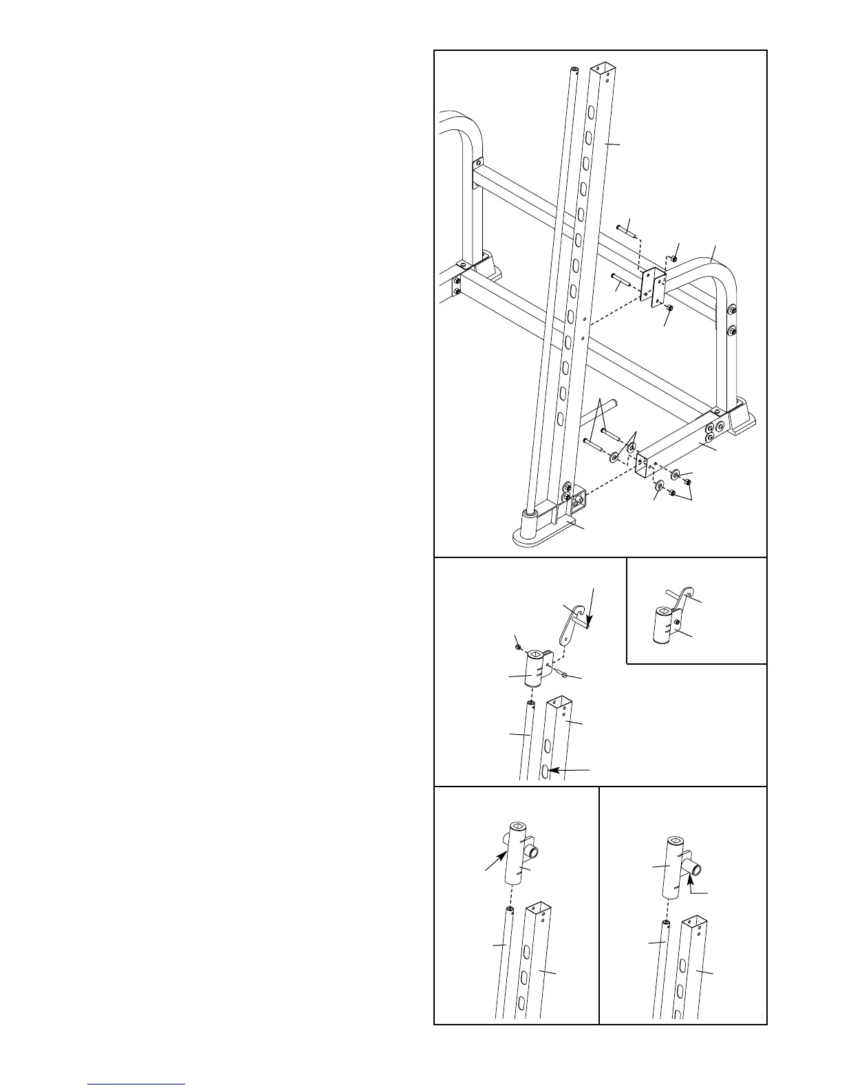
15. Using a rubber mallet, tap the left Rack Foot (35)
into the indicated Base (28). Attach the Foot to
the Base with two M10 x 65mm Button Bolts (60),
four M10 Washers (67), and two M10 Nylon
Locknuts (69). Do not tighten the Locknuts yet.
Attach the Left Upright (31) to the Rear Support
(29) with two M10 x 68mm Button Bolts (79) and
two M10 Nylon Locknuts (69). Do not tighten the
Locknuts yet.
Attach the right Rack Foot (not shown) and
Right Upright (not shown) in the same man-
ner.
16. Attach the Right Spotter Hook (39) to a Safety
Spotter (38) with an M8 x 12mm Shoulder Bolt (57)
and an M8 Nylon Locknut (72). Make sure the
bolt head is on the same side as the handle.
Slide the Safety Spotter (38) onto the right Guide
Bar (32) and engage the Right Spotter Hook (39)
into an adjustment hole near the bottom of the
Right Upright (62).
Assemble the Left Spotter Hook (40) and a
Safety Spotter (38) in the same manner.
15
16
79
79
69
69
67
67
67
60
69
29
31
35
28
40
39
38
38
57
32
62
Adjustment Hole
Handle
72
17. Identify the Left and Right Barbell Gliders (37, 81)
by the position of the screw holes.
Slide each Barbell Glider (37, 81) onto the Guide
Bar (32) next to the indicated Upright (31, 62).
Make sure the Barbell Gliders are oriented as
shown.
17
32
37
Screw
Hole
Screw
Hole
81
32
62 31
 Loading...