6
Assembly and connection manual | Agrónic 2500
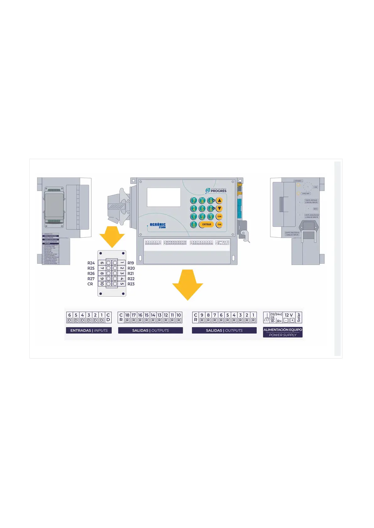
3 CONNECTION LOCATIONS
3.1. BOX FORMAT
In the box format, remove the bottom cover to access
the connectors.
To insert cables, the holes required must be punched
out (do this with the connection cover in place and
screwed in to avoid breaking it).
The 27-output model has the last nine outputs located
in a connector on the le side.
The connectors and antennas from the rest of the
options are located on the right side.
It is recommended to connect the wires to the terminal
using the terminal connectors that come with the unit.
(The terminals accept cables up to 2.5 mm
2
diameter).
Box format