30
5.3 MECHANICAL ENCODER
CIRCUIT BOARD CONNECTION
The circuit board is a controlling device equipped with:
12Vdc power, 25A max ;
Working contact
12Vdc, 25 A max motor output with polarity control
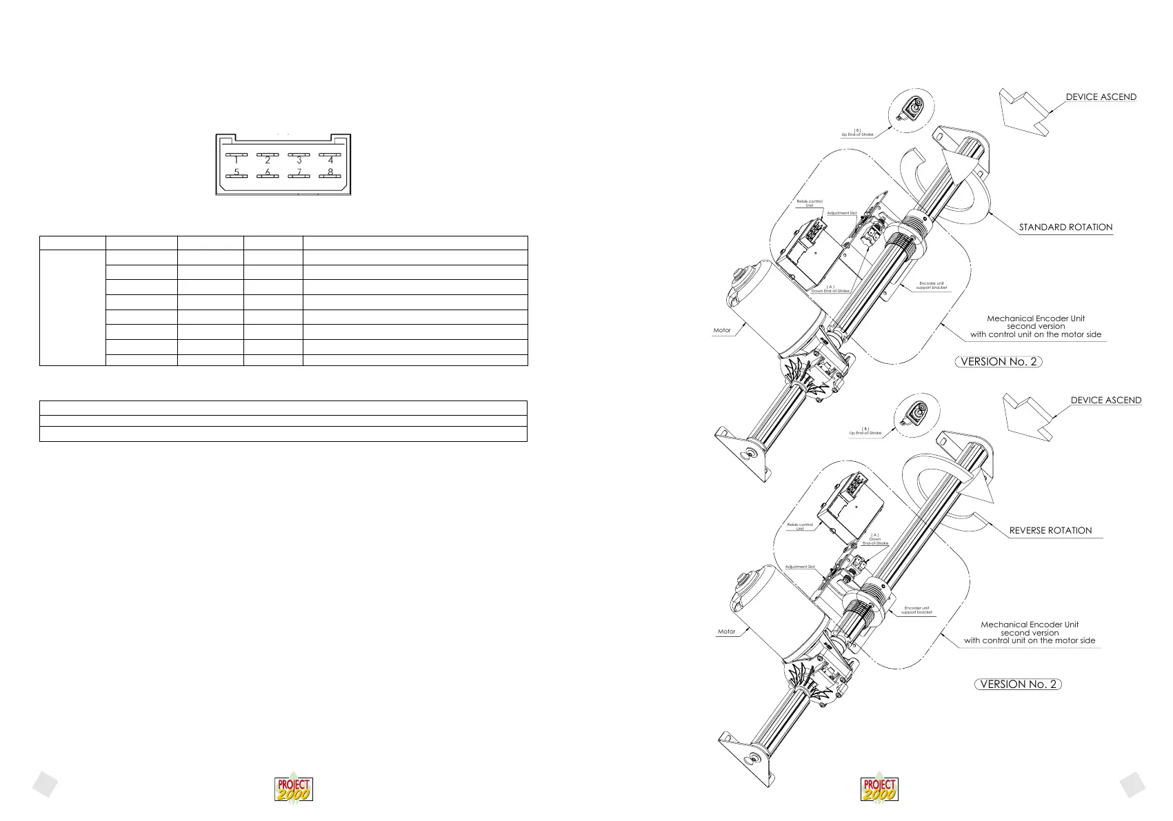
(C-1) PICTURE 1 – FASTON CONNECTOR, CONTACTS, SIDE VIEW
- Power
DC CURRENT VOLTAGE (nominal) 12Vdc
TOLERANCE: – 10% / + 20% (* note)
DC CURRENT VOLTAGE (MIN÷MAX): 10,8 ÷ 14,4 Vdc
(*note) The value indicated takes into account average motor features and estimated work load. The value indicated here is the mini-
mum value guaranteed for the system to work at maximum declared load.
With reference to picture 1, voltage must be applied to clamps 4 and 8 of the 8-pole faston connector, making sure to connect the
positive pole with the clamp and the ground to clamp 4.
5.3.1 ASSEMBLING AND HARNESSING PROCEDURE FOR THE ENCODER UNIT
Standard motor rotation (the belt shaft rotates in the direction shown by the arrow printed on the black plastic cover)
Connect the ORANGE wires to the “Down” end of stroke of the mechanical encoder and connect the YELLOW wires to the “Up”
end of stroke.
Reverse motor rotation (the belt shaft rotates in the opposite direction shown by the arrow printed on the black plastic cover)
In the control panel, invert the orange wire and the yellow wire.
Connect the YELLOW wires to the “Down” end of stroke of the mechanical encoder and connect the ORANGE wires to the “Up”
end of stroke.
1) While preparing the bed after preloading the belt by turning it twice around the shaft (and therefore after more or less setting the
lowest position for the bed), place the mechanical encoder bracket and insert the threaded sleeve into the shaft. Check the shaft rota-
tion when the bed is descending and consequently in which direction the anti-rotation tab is moving, place the end of stroke button
on the “mechanical encoder” bracket on the side on which the “anti-rotation” tab is moving when the bed is descending and fasten it
by tightening the 3 mm nut. Make sure that the sleeve on the shaft is fastened in the correct position and the “anti-rotation tab” has
enough room inside of the encoder bracket slot to slide throughout the whole ascent of the bed and that the ring nut on the bolt has
enough threading left to cover the bed ascent distance.
2) Move the bed upwards for a few centimetres lower the bed and check the exact stop position: if it does not match the desired
position, loosen the 14 mm bolt fastening the button and rotate the button to the extent that it is deemed necessary and try again to
lift and lower the bed. Repeat the operation until the desired position is reached. Remeber to fasten the 14 mm bolt.
We remind you of how to correctly check the end of stroke connection:
1) Control panel, by pressing the UP button the bed must go up and it must go down when pressing the DOWN button.
2) When pressing the end-of-stroke button while lifting the bed to the highest position, the bed must immediately stop. 29/06/2011
3) Press the end-of-stroke button (the one mounted on the mechanical encoder) to set the lowest position while lowering the bed: the
bed must immediately stop.
After doing this, check that the end of strokes are synchronized.
Silk-screen printing Logic ID Range Clamps Features - description
GND GND CN1 - 8 Negative power pole
MOT2 0 - 12Vdc CN1 - 7 Motor (grey)
- Not used CN1 - 6 Not used
F.C. (C-5) CN1 - 5 End-of-stroke (C-5) (orange)
+12 12Vdc CN1 - 4 Positive power pole
MOT1 0 - 12Vdc CN1 - 3 Motor (brown)
- Not used CN1 - 2 Not used
F.C. (C-4) CN1 - 1 End-of-stroke signal (C-4) (yellow)
(C-1)
English
English
Motor
( B )
Up End-of-Stroke
Adjustment Slot
( A )
Down End-of-Stroke
Relais control
Unit
Encoder unit
support bracket
Mechanical Encoder Unit
second version
with control unit on the motor side
VERSION No. 2
DEVICE ASCEND
STANDARD ROTATION
Motor
DEVICE ASCEND
REVERSE ROTATION
Encoder unit
support bracket
Mechanical Encoder Unit
second version
with control unit on the motor side
( A )
Down
End-of-Stroke
( B )
Up End-of-Stroke
Relais control
Unit
Adjustment Slot
VERSION No. 2
31
 Loading...