32 33
5.3.2 MOTOR CONNECTIONS
(C-3) PICTURE. 2 – MOTOR CONNECTOR, WIRE INLET, SIDE VIEW
The motor has a 5-pole connector for a female movable connector represented in picture 2. The picture shows the connector from the
cables connection side.
Wires No. 4 and 5 are motor connections, for the wiring please refer to diagram in picture 2.
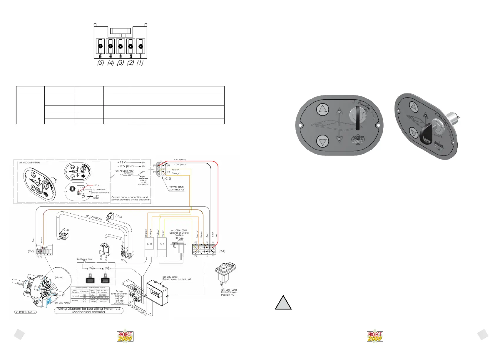
5.3.3 WIRING
PICTURE 3.A – WRING DIAGRAM
The diagram in picture 3.A summarizes all of the connections between the board and the other items that should be established in
order for the system to work correctly.
The motor connections (pin 3 and 7 of the 8-pole connector) and power connections (pins 4 and 8 of the 8-pole connector) must be
carried out exactly as shown in the picture, paying attention to use cables with a minimum section of 4 mmq.
Follow the instructions provided with the bed lifting system (wiring diagram).
Comply with current CEI regulations during the installation operation.
The Manufacturer provides a set of standard cables for installation with the bed lifting system. After electric installation it will be pos-
sible to start up and test the system.
The Manufacturer shall be held harmless for any bed lifting system malfunctioning caused by not perfectly functioning elec-
tric system connections and to an wrong installation on the vehicle.
5.3.4 STARTING AND OPERATING
PICTURE 4.A – CONTROLLER FRONT PANEL WITH MECHANICAL ENCODER
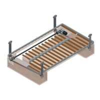
The bed moves vertically in a specic structure developed to this purpose and its stroke is limited by two ends:
- on the upper side, the stroke is limited by an end-of-stroke sensor;
- on the lower side, the limit is represented by the lowest position set, BY MEANS OF REGULATING THE END-OF-STROKE LOCATED ON
THE MECHANICAL ENCODER.
The bed can be lifted or lowered through activation in “ON” position of the key switch located on the panel and
by pressing the arrow-shaped switches on the front panel. When pressing the UP (arrow up) switch the bed will be lifted and it will go
down when pressing the DOWN switch.
Two green LED-lights are located on the controller panel and they will simultaneousely switch on. Durante il movimento del letto sarà
acceso solo il led corrispondente al senso di marcia.
The bed will be moving until you keep pressing the switch and it will stop when:
The switch is released;
A pre-set stop position is reached;
The bed is being lifted and the end-of-stroke position is reached.
The bed will move by pressing one of the switches again, unless one of the following conditions is detected:
The bed is in the end-of-stroke position and the UP switch is kept pressed;
The bed is in the lower programmed position and the DOWN switch is kept pressed.
In these two situations the bed will not move because the pre-set end-of-stroke positions for operation are reached and it is not pos-
sible to overcome them.
WARNING!
Be very careful when operating the bed lifting system
and make sure children are not standing in the bed lifting system operation area
Silk-screen printing Logic ID Range Clamps Features - description
MOT2 0 - 12Vdc PIN 5 Motor (GREY)
MOT1 0 - 12Vdc PIN 4 Motor (BROWN)
Not used PIN 3 Not used
Not used PIN 2 Not used
Not used PIN 1 Not used
(C-3)
!
English
English
art. 080-40013
VERSION No. 2
Wiring Diagram for Bed Lifting System V.2
Mechanical encoder
(4)
(5) (7) (8)
(4)(3)(1)
(C-3)
(5) (4)
+ 12 V
Brown
Grey
Orange*
(3)
Yellow*
Orange
Yellow
red
Black
(1)
Grey
Brown
+ 12 v (Red)
- 12 v (Black)
(3)
- 12 V (GND)
(1)
FOR ASCENT AND
DESCENT
COMMANDS
(2)
(4)
Yellow*
(2)
Orange*
Orange
4 Way
male
connector
Power and
commands
(C-2)
(C-5) (C-4)
(C-5)
(C-2)
(C-3)
(C-4)
(C-1)
art. 080-00038
art. 600-068-1-ZF00
Control panel connections and
power provided by the customer
Down command
+ 12 V
- 12 V
(GND)
Up command
art. 080-30031
Relais power control unit
Down
End-of-Stroke
Position
(A) NC
on the
encoder
art. 600-895-0-ZF00
art. 080-10001
Up End-of-Stroke
Position
(B) N.C.
art. 080-10001
End-of-Stroke
Position NC
(C-1)
(Motor)
Belt Safety Lock
NC
Connection table End-of-Stroke Position
Motor
Rotation
Connector
Wiring
Color
Device E.-of-S.P.
by connect
Standard
(C4)
Yellow
080-10001
(C5)
Orange
600-895-0-ZF00
Reverse
(C4)
Yellow
600-895-0-ZF00
(C5)
Orange
080-10001
 Loading...