
T
Tommy FullerAug 1, 2025
What to do if the fuse is blown in Projecta IntelliJay PM300-BTJ Power Supply?
- MMr. Dakota AllenAug 1, 2025
If your Projecta Power Supply displays 'Fuse blown', you should check the load and replace the fuse.
What to do if the fuse is blown in Projecta IntelliJay PM300-BTJ Power Supply?
If your Projecta Power Supply displays 'Fuse blown', you should check the load and replace the fuse.
Essential safety warnings for product usage and handling.
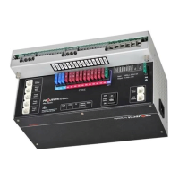
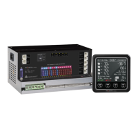
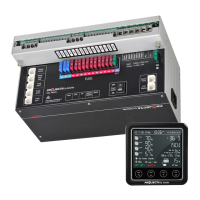
Details the main components of the PM300-BTJ and PM335J-NODE systems.
Lists the key features and capabilities of the power management systems.
Describes the LCD monitor as a digital control center for the transformer unit.
Explains the water tank probes and their monitoring capabilities.
Details the accepted input sources for the PM335J transformer unit.
Explains the multi-stage charging process for the house battery.
Describes the unit's function as a 12.8VDC power supply without a battery.
Details the built-in Maximum Power Point Tracking solar charger.
Explains the function of the Voltage Sensitive Relay for battery charging.
Outlines the 14 outputs categorized for different loads and controls.
Describes the protection feature that disconnects loads at low battery voltage.
Explains the power switch for cutting off the charger and outputs.
Details the system for measuring battery voltage, current, and capacity.
Describes the PM300-BTJ and PM335J-NODE systems' structure.
Provides dimensions and installation instructions for the LCD monitor.
Details dimensions and installation for PMWS400 and PMWS200 probes.
Lists the necessary components and their specifications for wiring.
Presents the overall system wiring diagram.
Covers cable size recommendations and terminal connection types.
Explains the status and meaning of the LEDs on the transformer unit.
Provides an overview of the LCD monitor's display and functions.
Details the meaning of various symbols shown on the LCD monitor.
Explains the functions of the switches on the LCD monitor.
Details how to configure battery settings and other parameters on the PM335J.
Explains the use of a remote switch to control output loads.
Guides through accessing and using the LCD monitor's configuration menu.
Instructions for pairing the system with a smartphone via Bluetooth.
Explains how to use the mobile app for monitoring and control.
Guidelines for accurate battery SOC monitoring and maintenance.
Routine checks for daily upkeep of the power management system.
Explains the meaning of LED status lights for troubleshooting.
Lists and explains error codes displayed on the LCD monitor.
| Input Voltage | 100-240V AC |
|---|---|
| Output Voltage | 12V DC |
| Output Current | 12.5A |
| Power | 300W |
| Frequency | 50/60Hz |
| Efficiency | 85% |
| Cooling | Fan cooled |
| Dimensions | 215 x 115 x 50 mm |
| Weight | 1.2 kg |
| Protection Features | Over Voltage, Short Circuit, Over Temperature |
| Storage Temperature | -20°C to 70°C |