Power source
The T1100 is powered by a 24 VAC
power source connected using the
"COM" pin and the "24 AC" pin (see
N
L
120Vac24Vac
24 VAC
COM
1
2
3
4
Figure 3). The common for the
power source is shared by the
auxiliary analog input and the analog
output.
Figure 3: Power Source
Network Setup
RS485
Daisy
Chain
NET A (+)
NET B (-)
1
2
3
4
The T1100 can work autonomously
or networked. When networked, it
will communicate in real-time with
other ProLon controllers. The T1100
uses the Modbus RTU protocol over
RS485. A unique network address
must be assigned to each device on
the network. For the T1100, this can
be done through the menu system.
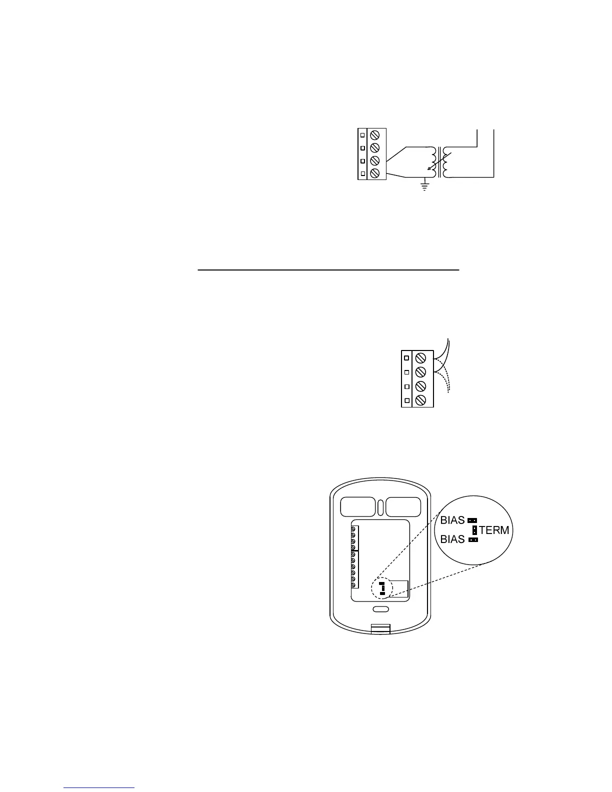
The network connections are made
using the “NETA” (+) and “NETB” (-)
pins (
Figure 4: Network Connection
Figure 4). Bias and terminating
resistors can be activated or
deactivated using jumpers on the
back of the PCB (see
Figure 5). Bias
and terminating resistors are used to
improve signal quality in an RS485
network. For more information
regarding application of network
resistors or shielding, see the
ProLon Network Guide.
Figure 5: Network Resistor Jumpers
2