Do you have a question about the Prolon T1100 and is the answer not in the manual?
Overview of visualization and options settings.
Overview of configuration settings for temperature, outputs, calibration, and network.
Parameters for Proportional-Integral control loops.
Limits for heating and cooling setpoints.
Configuration parameters for the digital output.
Configuration parameters for the analog output.
Proportional and integral settings for radiant floor control.
Network communication settings including baud rate, parity, and stop bits.
Communication port settings.
Select between Celsius and Fahrenheit temperature display.
Determines how zone temperature is calculated (Internal, External, Average).
Resets configuration properties to factory defaults.
Sets the network address for the thermostat.
Applies an offset to the room temperature reading.
Deadband between occupied heating and cooling setpoints.
Time for heating integral component to equalize proportional component.
Low limit for heating setpoint during occupied mode.
Decrease in active heating setpoint during unoccupied mode.
Sets digital output to heating or cooling mode.
Sets digital output to proportional or differential mode.
Manually overrides digital output or returns to automatic control.
Sets analog output to heating or cooling mode.
Sets analog output to proportional or differential mode.
Configures analog output to pulse instead of modulate.
Sets the analog output voltage range (0-10V, 2-10V, 0-5V).
Assigns output to control radiant floor system.
Maximum slab temperature limit for radiant floor control.
Pulse output at 50% cycle length when slab temp reaches setpoint.
Total time for an ON and OFF cycle.
First control group assignment for the thermostat.
Weight of thermostat in the selected GrpCode1.
Baud rate used for serial communication.
Parity used for serial communication (None, Odd, Even).
Specifications for the digital output functionality.
Specifications for the analog output functionality.
Communication protocols used by the thermostat.
| Brand | Prolon |
|---|---|
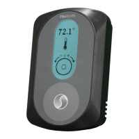
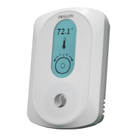
| Model | T1100 |
| Category | Thermostat |
| Language | English |