6 Functional description
6.1
Liquid End
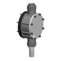
The dosing process is performed as follows: The diaphragm is pressed
into the dosing head; the pressure in the dosing head closes the suction
valve and the feed chemical flows through the discharge valve out of the
dosing head. The diaphragm is now drawn out of the dosing head; the dis‐
charge valve closes due to the negative pressure in the dosing head and
fresh feed chemical flows through the suction valve into the dosing head.
One cycle is completed.
6.2 Drive unit
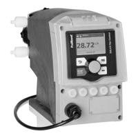
The displacement body is driven by an electromagnet, which is controlled
by an electronic control.
The optoDrive
®
drive technology means the variation over time of the
metering flow can be precisely matched to the requirements of the partic‐
ular application. Hence the user can, dependent on requirements, set a
slow discharge stroke for nearly continuous metering or a quick stroke e.g.
for quick clocked filling processes. In both operating modes it is possible,
to selectively also slow the suction stroke, see figure. In this way, it is pos‐
sible to prevent the main cause for imprecise metering with high viscosity
feed chemicals, namely the incomplete filling of the liquid end. For the
case of gaseous feed chemicals, the slow suction stroke prevents cavita‐
tion and consequently increases metering accuracy. Oscillations in the
back pressure in the metering line, which could lead to undesirable varia‐
tions in the metering volume, are automatically compensated for by the
drive. Consequently, a dosing precision is attained, which otherwise could
only be achieved using a complex control circuit.
p Pressure
t Time
The integral injection point monitoring of the hydraulic metering parame‐
ters, optoGuard
®
is integrated in the drive. It automatically detects blocked
points of injection or broken metering lines. Consequently, dependent on
the hydraulic installation situation, separate relief valves and pressure sen‐
sors need not be used, and no uncontrolled metering through a broken
line occurs. It also detects air or gases (airlock) trapped in the liquid end.
This prevents metering of incorrect quantities and thus increases process
reliability. The relevant messages are shown on the pump's display. The
system operator can determine, depending on the type of fault, whether a
message is to be sent to the process control system via the fault signal
relay and whether metering is automatically stopped.
6.3
Capacity
The capacity is determined by the stroke length and rate.
optoDrive
®
drive technology
Fig. 6: Metering types: a) pulsing, b)
nearly continuous
Functional description
22




 To Next Page