BM-16
This document is protected by copyrights.
Copying, using, or distributing without permission of PROMOTECH is prohibited.
10
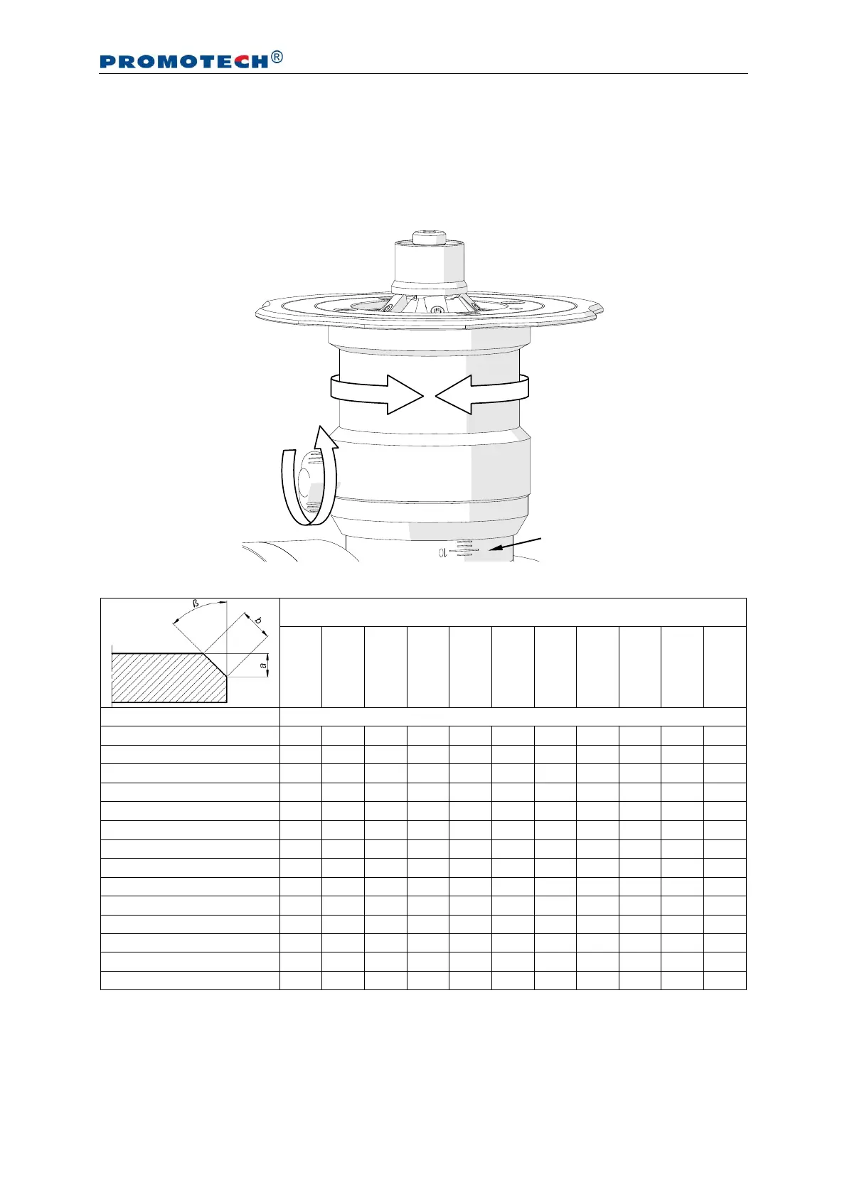
3.2. Adjusting the bevel parameters
Unplug the machine from the power source. Next, loosen the clamping screw (1,
Fig. 5), rotate the sleeve (2) in such a way that the scale 3 shows the required bevel
height ‘a’ (Tab. 1), and then re-tighten the screw.
Fig. 5. Adjusting the bevel parameters
Tab. 1. Relation between bevel width and height of the available milling heads