4.1
1 hFE Measurement:
1. Switch the function to hFE range.
2. Check the transistor is NPN or PNP type, insert the emitter, base and
collector separately to the correct hole, the approximate value will be
displayed on LCD.
4.12 Diode and Continuity Test:
1. Connect the BLACK test lead to “COM” jack and RED test lead to the
“VΩHz” jack. (Notice the RED test lead should be +)
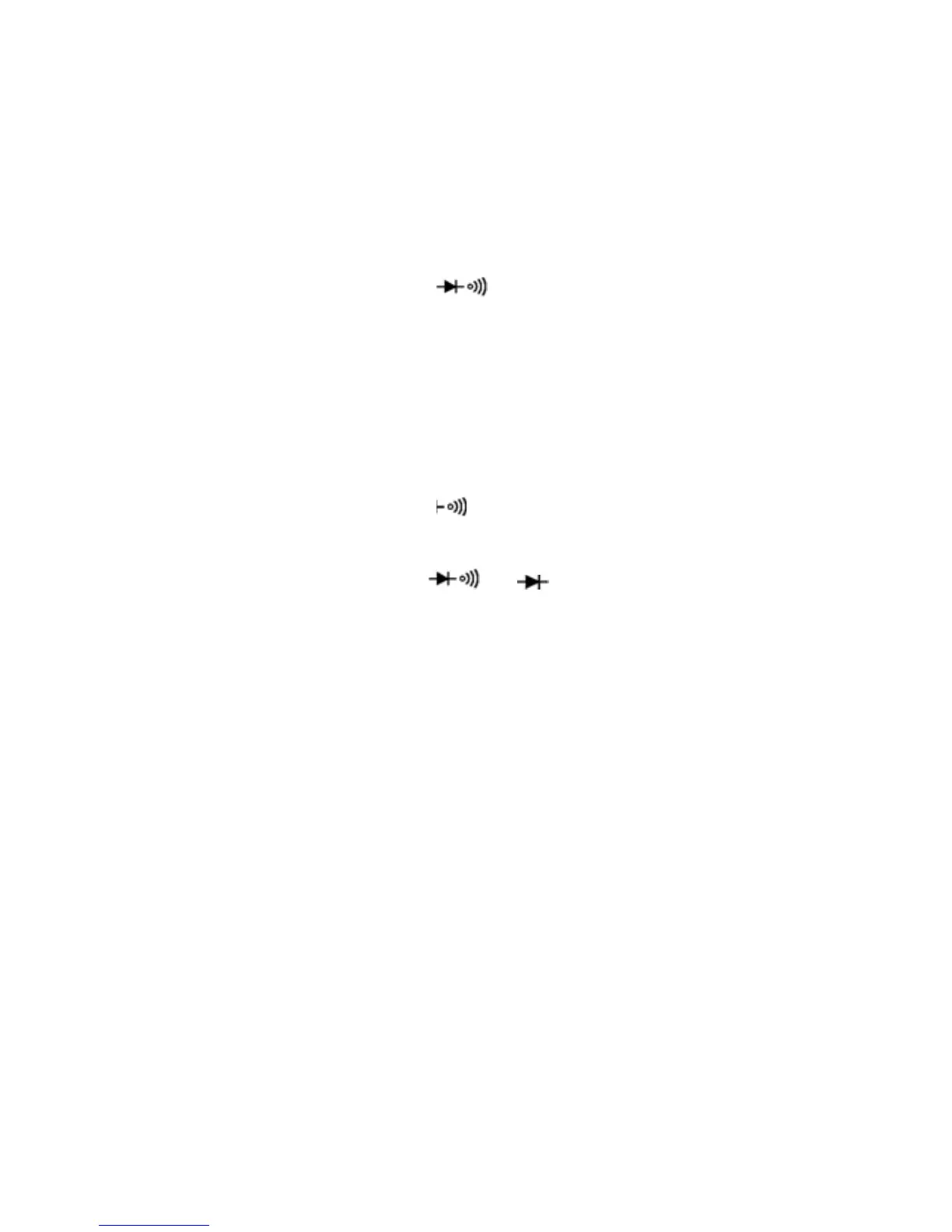
2. Switch the FUNCTION to “
”, and test the diode.
3. Forward measurement: Connect RED test lead to the positive of the test
diode, BLACK test lead to the negative, then, reading of approx. forward
voltage of this diode will be displayed on LCD.
4. Reverse measurement: Connect BLACK test lead to the positive of the
test diode, RED test lead to the negative, the mark "OL" will be
displayed.
5. Complete diode test should include both steps. If the result doesn’t meet
above result, it means the diode is out of order.
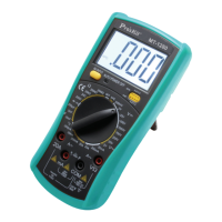
6. Switch the FUNCTION to “
” range.
7. Connect the test probes to two points of circuit, if the resistance is lower
than 50Ω, Buzzer will sound.
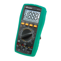
Note: Do not input voltage at
or range.
4.13 Temperature Measurement:
1. Switch the function key to “℃/℉”range.
2. Insert two ends of the temperature sensor into “COM” and “VΩHz” jack,
and connect the work-point to the place where wanted to take
temperature. The value will be displayed on LCD.
3. Press”Select” key to select centigrade/
Fahrenheit mode.
NOTE:
1. When the input terminal is in open circuit, it will display the “normal
temp.”
2. Do not change the thermocouple, or the accuracy can not be secured.
3. Do not input voltage at this range.
4.14 Data hold:
Press “Hold” key, and the current data will be displayed on LCD; Press the
key again, and it will cancel the hold function.
4.15 Backlight:
Press “Hold” key for 2 sec. to turn on the backlight, and it will be
automatically off after 10 sec.
9