OPTIMAX
®
25
Installation Data
English
®
Through the wall mounting “film output”
Film output to the light room for OPTIMAX
®
processor
Type 117x-y-6000
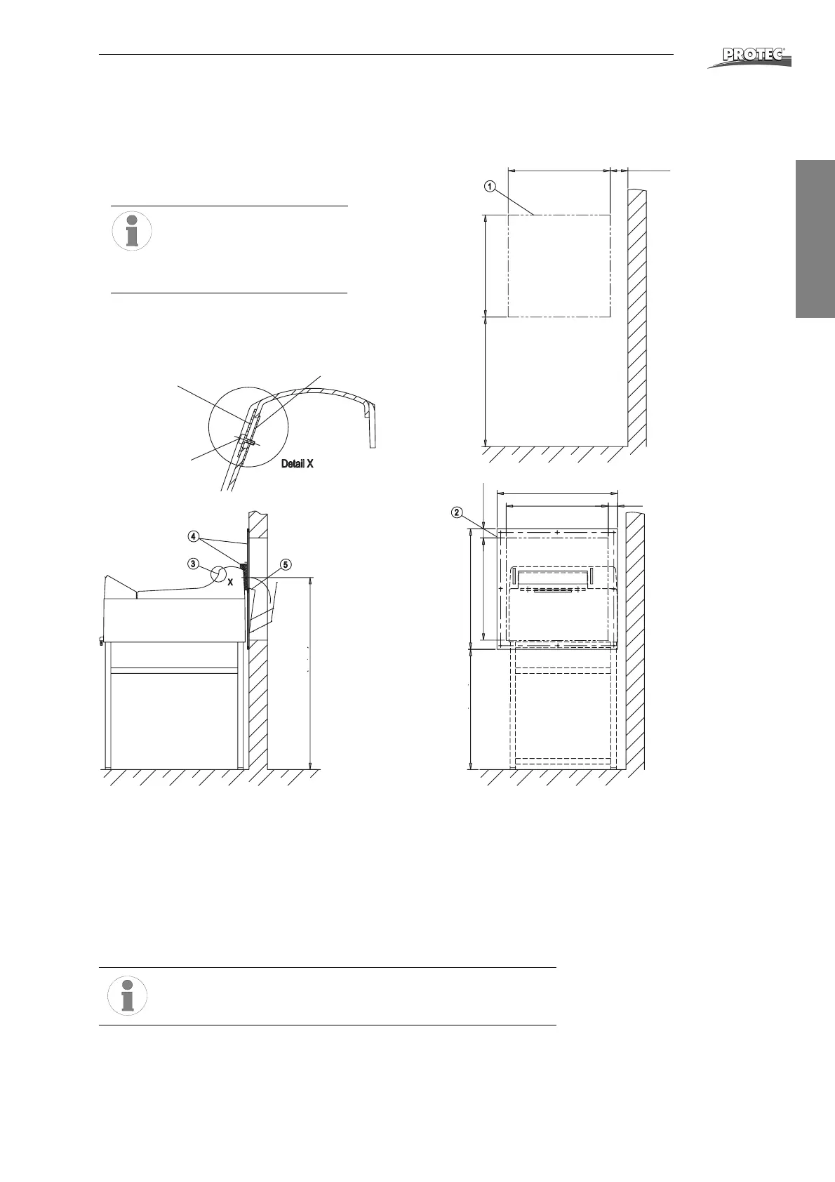
1. Wall opening according to drawing.
2. Fasten wallplate with enclosed eight screws (note markings).
3. Fix blind plate with screws and straps on the film outlet (Detail X).
4. Push processor up against wallplate and place foam rubber light protection
between processor and wallplate.
5. Hang in film catch basket at wallplate from the backside.
6. Check mounting-set for light imper-meability and function.
Please notice:
Pull sealing wedge off before removing machine cover.
1
.
0
4
0
m
m
(
4
0
,
9
”
)
7
0
5
(
2
7
,
7
”
)
5
5
3
(
2
1
,
7
”
)
553 (21,7”) min. 100 (3,9”
6
5
3
(
2
5
,
7
”
)
6
5
5
(
2
5
,
8
”
)
5
5
3
(
2
1
,
7
”
)
5
0
(
1
,
9
6
”
)
653 (25,7”)
553 (21,7”) 50 (1,96”)
Wall break through
for film exit
Blind plate
1176-0-0607
Strap
1253-0-0203
Screw
M4x20
3079-8-5043
705 mm (27.7“)
Lower edge of wall plate
655 mm (25.8“)
1040 mm (40.9“
Film exit height
All dimensions refer to PROTEC
®
base table OPTIMAX
®
(1267-0-0000)
Dimensions in mm